Foundation Underpinning

Foundation Underpinning

Load-transfer technique that carries existing foundation loads past failing soil into deeper bearing strata or anchored ground. Includes micropile underpinning, battered soil anchors, and foundation tie-backs.

50-500 kip
Pile Capacity
100-600 kip
Anchor Capacity
6 ft
Min Headroom
75+ yr
Design Life
Overview

Understanding Underpinning

Foundation underpinning is a load-transfer technique that carries existing foundation loads past unstable or inadequate soil into deeper, more competent bearing strata or anchored ground beyond the failure zone. Three method families cover the work: micropile underpinning, battered soil anchors, and foundation tie-backs, which differ in element angle and the load condition each is sized for. Underpinning is a focused scope within the broader category of foundation repair, which also includes crack repair, slab leveling, drainage correction, and waterproofing.

What Is Foundation Underpinning?

Foundation underpinning is a load-transfer technique that carries existing foundation loads past unstable or inadequate soil and into deeper, more competent bearing strata or anchored ground beyond the failure zone. The terms underpinning, battered soil anchors, and foundation tie-backs all describe variations of the same load-transfer mechanism, distinguished by element angle and the load condition each is sized for. Drilled-and-grouted underpinning entered codified US practice through Federal Highway Administration documents in the 1990s and 2000s, with FHWA GEC-7 (Micropile Design and Construction) serving as the canonical practitioner reference and AASHTO LRFD §10.9 governing load and resistance factors for permanent installations on transportation projects.

Underpinning is one focused scope within the broader category of foundation repair, which also covers crack repair, slab leveling, polyurethane foam injection, drainage correction, and waterproofing. The selection driver is the diagnosis. When the foundation has settled, moved laterally, or needs added capacity for new loads, underpinning is the appropriate tool. When the symptoms are surface cracking without movement, water intrusion, or a slab condition independent of the structural foundation, shallow remediation alone is sufficient.

Key Benefits

  • Works in 6 feet of headroom inside occupied basements
  • Low vibration installation, safe for historic and adjacent structures
  • Capacity verified by load test on critical elements
  • Adapts to any soil or rock condition
  • Permanent solution with 75+ year design life
The Engineering

How Foundation Underpinning Works

How the system carries load in service, and how we build it on site.

Construction begins with foundation evaluation: an existing-conditions survey, a subsurface investigation to locate competent bearing material, and a load determination for each support point. The structural engineer assigns capacity and geometry to each underpinning element. Drill rigs, frequently the low-headroom variants that operate in 6 feet of clearance inside basements or under existing structures, advance boreholes adjacent to or through the existing footings on the designed pattern. A high-strength steel reinforcing element is inserted with centralizers, and neat cement or sand-cement grout is placed in the annular space, bonding the element to the surrounding ground.

Load transfer follows a defined column. Lateral or vertical load travels from the existing foundation into a structural connection, typically a pile cap, bracket, or grade beam, then into the steel element in tension, compression, or both, and finally into the bond zone where grout-to-ground friction transfers load into competent bearing material below the failure zone. Where lateral movement is the driver, elements are installed on a batter so a single bar resists combined vertical and horizontal load. Where wall restraint is the driver, elements terminate at the back face of the foundation wall and are post-tensioned against a bearing plate. Critical elements are verified by load test before the connection is finalized.

1

Foundation Evaluation

Existing-conditions survey, subsurface investigation, and load determination per support point.

2

Element Layout

Engineer-designed pattern, batter angle, and capacity for each underpinning element.

3

Drill and Install

Boreholes advanced adjacent to or through existing footings; steel reinforcement inserted with centralizers.

4

Grout and Connect

Cement grout placed by tremie; load transfer connection (pile cap, bracket, or grade beam) constructed.

5

Load Test and Verify

Critical elements load-tested per FHWA GEC-7 or PTI DC35.1 before final lock-off and connection.

System Variants

Types of Foundation Underpinning

Type 01

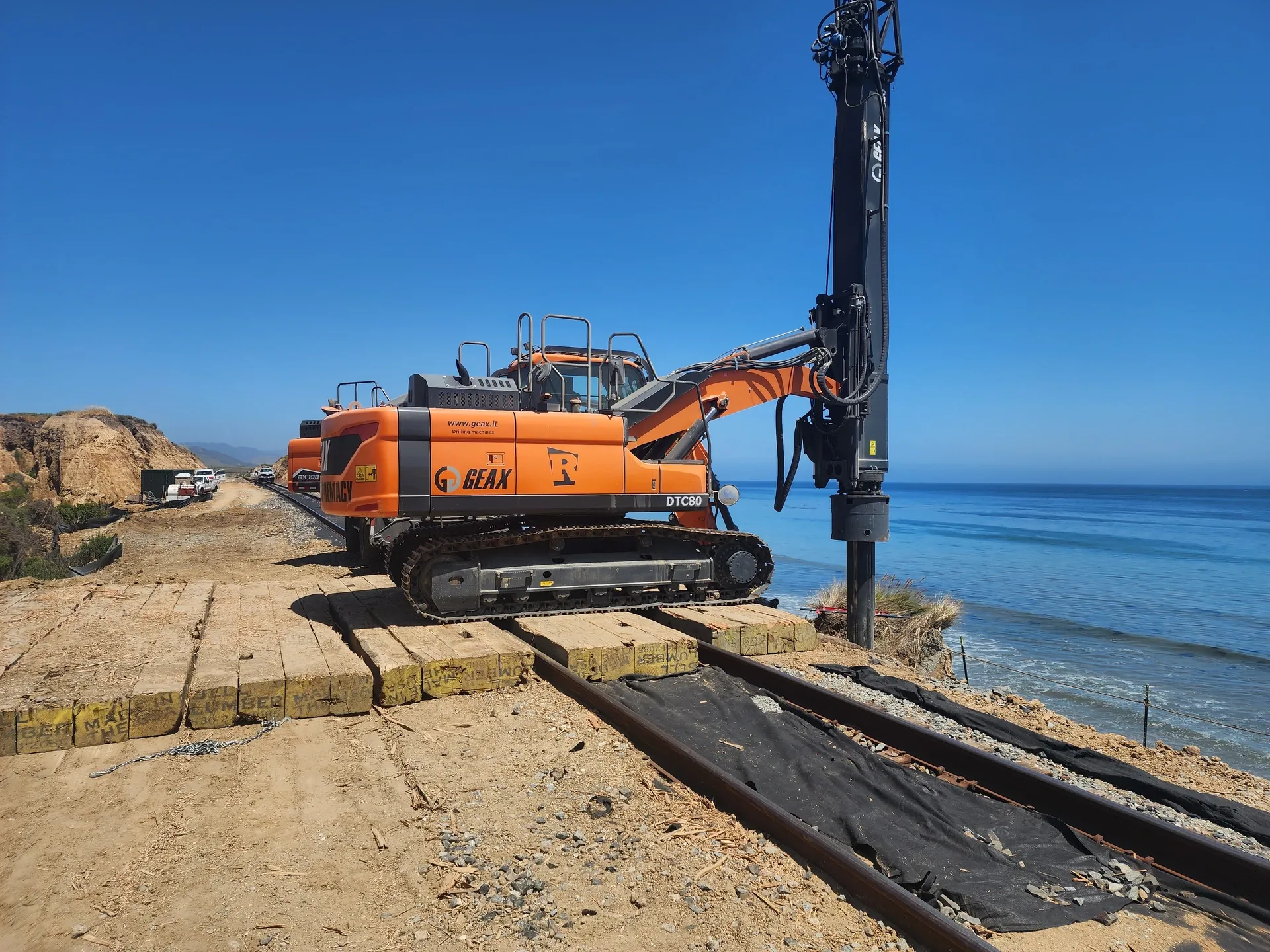
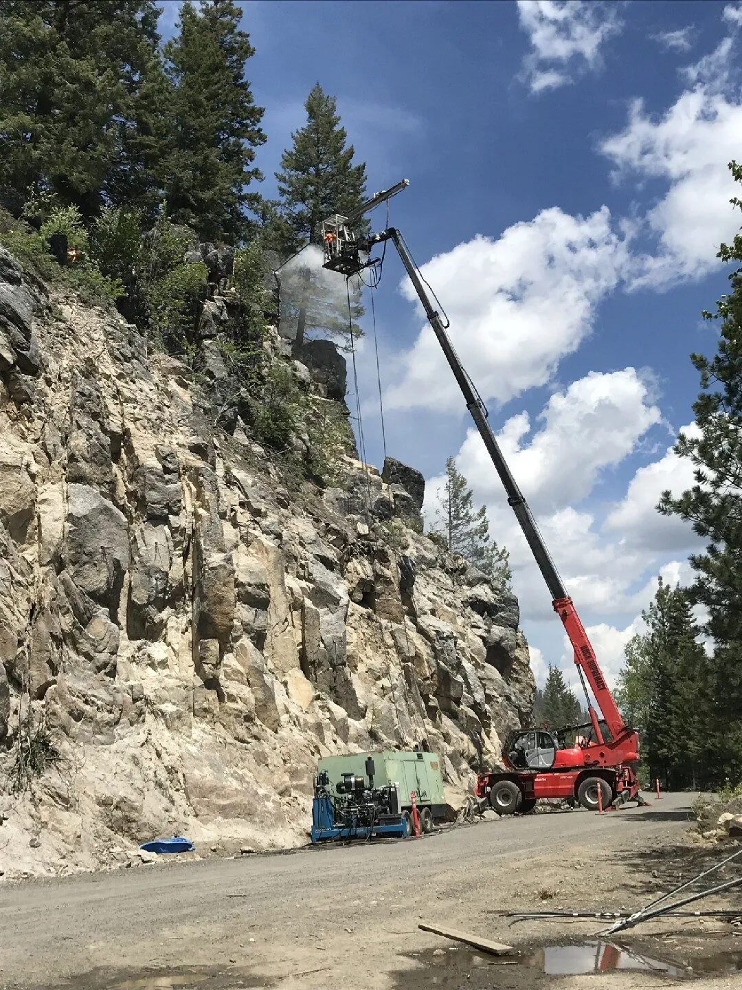
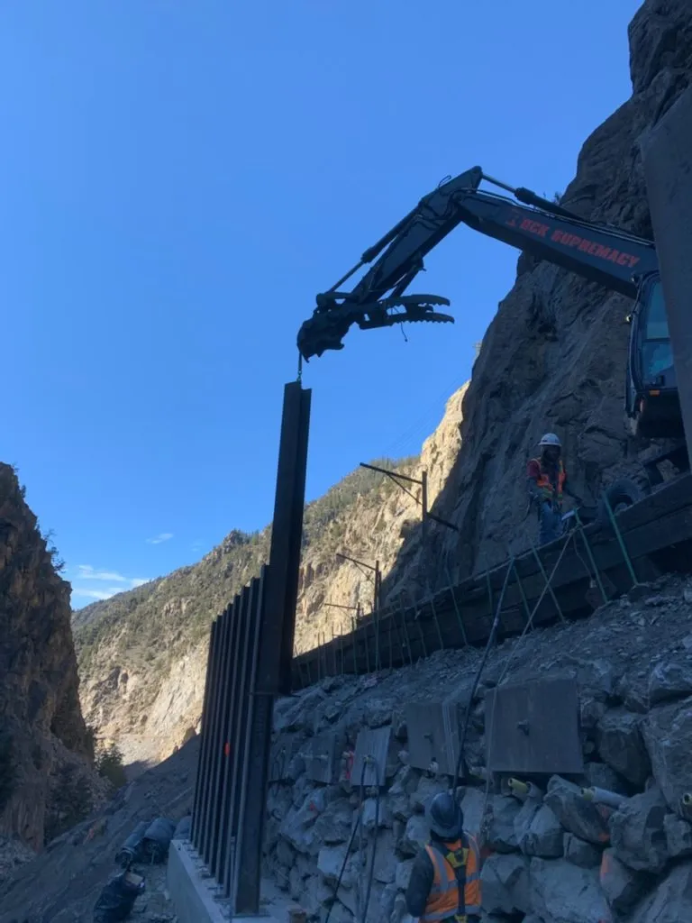
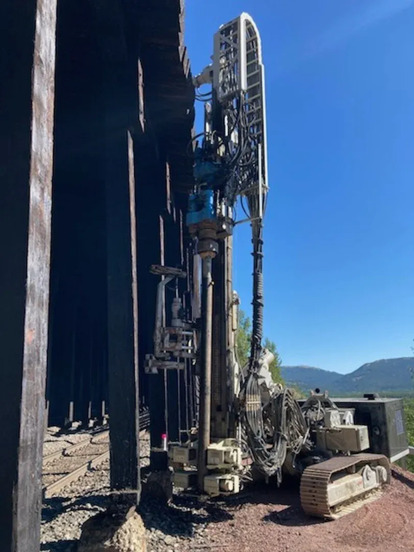
Micropile Underpinning

Drilled-and-grouted small-diameter piles, typically 4 to 12 inches in diameter, with working capacities ranging from 50 to 500 plus kips per pile. Installed vertical or on a slight batter using rotary or rotary-percussive equipment, including low-headroom rigs that operate in as little as 6 feet of clearance, which makes the technique the default choice inside occupied basements and under existing structures. Reinforcement is solid threaded bar or hollow self-drilling bar depending on ground conditions, and grout is placed by tremie line from the toe of the hole upward. The full deep-dive, including variations and design parameters, is on the micropile underpinning page.

Type 02

Battered Soil Anchors

The same drilled-and-grouted hardware family as a micropile or a soil nail, installed at a downward batter angle in the 15 to 45 degree range so a single element resists both vertical foundation load and lateral earth pressure in one bar. Sizing follows the FHWA GEC-7 bond and structural framework, with element angle selected to align with the resultant load vector at the foundation. Battered anchors are the appropriate tool when foundation movement is slope-driven rather than pure settlement, for example a hillside footing translating downslope, a retaining structure rotating outward at the toe, or a wing wall pulling away from a bridge abutment. Capacity is verified by load test on critical elements.

Type 03

Foundation Tie-Backs

Post-tensioned anchors terminating at the back face of a foundation wall or the underside of a footing, restraining the foundation against lateral earth pressure. The anchor is drilled into stable ground beyond the active failure surface, grouted along a bonded fixed length, and then post-tensioned against a bearing plate to lock the foundation in position. Capacities run from 100 to 600 plus kips per anchor. Used to stabilize bowing basement walls, restrain spread footings under uplift, anchor down retaining structures resisting overturning, and tie existing foundations to bedrock for seismic retrofit. The deep-dive on anchor design, testing, and PTI corrosion-protection classes is on the tieback anchors page.

Side By Side

Foundation Underpinning vs Adjacent Techniques

VS

Foundation Underpinning vs Foundation Repair

Foundation repair is the umbrella scope of work performed on a damaged or inadequate foundation. It covers underpinning, but also crack repair, slab leveling, polyurethane foam injection, drainage correction, basement waterproofing, and surface restoration. Underpinning is the specific subset that transfers structural load into deeper bearing strata via drilled-and-grouted elements, and is the right tool when the diagnosis is settlement, lateral movement, or insufficient capacity for a planned added load. Foundation repair as a service typically packages underpinning with the other scopes that the building actually needs, sized to the specific failure mode rather than applying load transfer where shallower remediation would do.

VS

Underpinning vs Shallow Soil Remediation

Underpinning transfers load past the failure zone via a structural element. Shallow soil remediation, including pressure grouting, compaction grouting, and polyurethane foam injection, densifies or lifts soil in place. The selection driver is the depth of the failure zone. When loose or compressible soil extends only a few feet below the footing and competent bearing is shallow, compaction grouting or foam injection can stabilize and re-level without installing piles. When the failure zone extends deeper than economical shallow treatment, or competent bearing is materially deeper than the existing footing, underpinning is required. On many projects the two combine: underpinning carries the structural load, while pressure grouting fills voids and improves the surrounding soil.

VS

Battered Anchors vs Vertical Micropiles

Both use drilled-and-grouted reinforcing elements bonded to competent ground. The difference is geometry and the load condition each is sized for. Vertical or near-vertical micropiles are sized for compression or tension along the pile axis, which matches a settlement-driven foundation problem where the load vector is essentially vertical. Battered anchors are installed at 15 to 45 degrees of declination so a single element resists combined vertical and horizontal load, which matches a slope-driven foundation problem where the resultant load vector is inclined. The two are routinely combined on a single foundation when both load conditions are present.

Not sure which system fits? We'll walk through the tradeoffs for your site conditions.

Talk Through Your Options
Where It Fits

Common Applications and Project Types

Settlement repair on existing residential and commercial foundations is the largest application class, including settling chimneys, sinking additions, and footings on compressible fill. Slope-driven foundation movement on hillside structures, where the foundation is translating downslope rather than settling vertically, is the typical battered-anchor application. Capacity increases on existing foundations to support added stories, mezzanine loads, or new equipment foundations are common in commercial and industrial retrofit. Bridge abutment and pier rehabilitation, where scour or long-term settlement has compromised bearing, accounts for the dominant transportation-sector application. Seismic retrofit anchoring existing foundations to bedrock or competent strata, and historic structure stabilization where the original foundation is on inadequate bearing, round out the typical project mix. Owners selecting an underpinning contractor should confirm that crews have demonstrable experience with low-headroom installation and structural connection design, since the load transfer detail at the existing foundation is where most underpinning failures originate.

Settlement repair on existing foundations
Hillside foundations with slope-driven movement
Capacity increase for added loads or new stories
Bridge abutment and pier rehabilitation
Seismic retrofit anchoring to bedrock
Historic structure stabilization
Bowing basement wall restraint
Codes And References

Engineering Standards and References

FHWA

GEC-7

Micropile Design and Construction

Geotechnical Engineering Circular No. 7. The canonical practitioner reference for drilled-and-grouted underpinning elements, covering bond capacity, structural design, load testing, and corrosion protection.

AASHTO

LRFD §10.9

Bridge Design Specifications, Drilled Deep Foundations

Defines load and resistance factors and minimum design life framework for permanent underpinning elements on transportation and AASHTO-governed projects.

PTI

DC35.1

Recommendations for Prestressed Rock and Soil Anchors

Governs post-tensioned tieback anchor design, acceptance testing, lock-off load criteria, and corrosion-protection classes for permanent foundation anchors.

Gallery

Our Work in Action

Questions

Foundation Underpinning FAQ

Foundation underpinning is a load-transfer technique that carries existing foundation loads past unstable or inadequate soil and into deeper, more competent bearing strata or anchored ground beyond the failure zone. The terms underpinning, battered soil anchors, and foundation tie-backs describe variations of the same load-transfer mechanism, distinguished by element angle and the load condition each is sized for. In the United States, drilled-and-grouted underpinning is codified in FHWA GEC-7 (Micropile Design and Construction) and AASHTO LRFD §10.9. Underpinning is one focused scope within the broader category of foundation repair, which also covers crack repair, drainage correction, and slab leveling.
Foundation underpinning works by drilling steel reinforcement past the failure zone into competent bearing strata, grouting the annular space to bond the element to the ground, and constructing a structural connection at the existing foundation that transfers load into the new element. Load travels from the existing footing into a pile cap, bracket, or grade beam, then into the steel reinforcement in tension or compression, and finally into the grout-ground bond zone deeper in the competent material. Where lateral movement is the driver, elements are installed on a batter so a single bar resists combined vertical and horizontal load. Each critical element is verified by load test before the connection is finalized.
Three families cover the great majority of installed work. Micropile underpinning uses small-diameter drilled-and-grouted piles, typically 4 to 12 inches in diameter, with working capacities from 50 to 500 plus kips per pile, installed vertical or on a slight batter, including with low-headroom rigs that operate in 6 feet of clearance. Battered soil anchors use the same hardware family installed at 15 to 45 degrees of declination so a single element resists combined vertical and lateral load, suited for hillside foundations and retaining structures. Foundation tie-backs are post-tensioned anchors terminating at the back of a foundation wall or footing, drilled into stable ground beyond the active failure surface and stressed to 100 to 600 plus kips per anchor.
Foundation repair is the umbrella scope of work performed on a damaged or inadequate foundation. It covers underpinning, but also crack repair, slab leveling, polyurethane foam injection, drainage correction, basement waterproofing, and surface restoration. Underpinning is the specific subset that transfers structural load into deeper bearing strata via drilled-and-grouted elements. The selection driver is the diagnosis. When the foundation has settled, moved laterally, or needs added capacity, underpinning is the appropriate tool. When the symptoms are surface cracking without movement, water intrusion, or a slab condition independent of structural settlement, shallow remediation alone is sufficient and underpinning is overkill.
Yes. Low-headroom drill rigs operate in clearances as low as 6 feet, which allows micropile underpinning inside finished basements, crawl spaces, and under existing first-floor slabs. Drilled installation produces no damaging vibration, so adjacent and historic structures remain undisturbed. Floor slabs are core-drilled or saw-cut on a designed pattern to provide drilling access, and the openings are restored after the load transfer connection is complete. Most residential and light commercial underpinning projects proceed with the building still occupied.
A battered soil anchor is a drilled-and-grouted reinforcing element installed on a downward angle, typically 15 to 45 degrees of declination, so a single element resists both vertical foundation load and lateral earth pressure in one bar. The hardware and installation method match a vertical micropile or a soil nail, but the geometry is selected to align with the resultant load vector at the foundation. Battered anchors are the appropriate tool when foundation movement is slope-driven rather than pure settlement, for example a hillside footing translating downslope, a retaining structure rotating outward at the toe, or a wing wall pulling away from a bridge abutment.
Properly designed micropile underpinning and tie-back anchors carry a 75 plus year design life when installed with corrosion-protected reinforcement and durable grout, per FHWA GEC-7 and PTI DC35.1. Permanent installations use galvanized or epoxy-coated bars, sacrificial steel allowance, or fully encapsulated tendons depending on the aggressiveness of the soil environment. Capacity is verified by load test at install, and there is no scheduled maintenance for the underpinning elements themselves. The typical limiting factor on long-term performance is the corrosion protection detail at the connection, which is addressed in design and field inspection.
In the United States, three primary references govern. FHWA GEC-7 (Geotechnical Engineering Circular No. 7), Micropile Design and Construction, is the canonical practitioner document for drilled-and-grouted underpinning, covering bond capacity, structural design, load testing, and corrosion protection. AASHTO LRFD Bridge Design Specifications §10.9 defines load and resistance factors for drilled deep foundations on transportation projects. PTI DC35.1, Recommendations for Prestressed Rock and Soil Anchors, governs post-tensioned tieback anchor design, testing, and corrosion protection. State DOT specifications typically reference these documents and add jurisdiction-specific testing and corrosion-protection requirements.
Testimonials

Client Testimonials

Trusted by DOTs, engineering firms, and property owners nationwide.

Contact

Deploy Us

Ready to discuss your project? Our team is standing by to assess your site conditions and develop a custom solution using Foundation Underpinning and other proven techniques.

Emergency (24/7)

(541) 383-7625

Bidding & Estimates

Info@RockSupremacy.com

Headquarters

Western Division (HQ)
65147 N Hwy 97
Bend, OR 97701
Eastern Division
915 Millennium Ct
Blountville, TN 37617

Licensed in CO, UT, WY, ID, MT, CA, WA, OR, TN, VA

Request Consultation