Pressure Grouting

Pressure Grouting

Pressure grouting injects fluid grout into soil pores, rock fractures, or open voids to densify loose ground, seal water pathways, fill cavities, and lift settled foundations. Compaction, permeation, fracture, and chemical grouting variants address different host-ground conditions.

10-600
psi Injection Range
3-10 ft
Hole Spacing
4 Methods
Compaction to Chemical
In-Situ
Ground Improvement
Overview

Understanding Pressure Grouting

Pressure grouting is the controlled injection of fluid grout into soil pores, rock fractures, or open subsurface voids to alter the engineering behavior of the ground in place. The method is a family of techniques rather than a single procedure, with compaction, permeation, fracture, and chemical grouting each driven by a different physical mechanism and selected for a different range of host ground. The shared principle is in-situ improvement: rather than excavating and replacing weak ground, the operator drills a small-diameter hole, isolates a treatment interval with a packer or sleeve port, and pumps grout under pressures monitored continuously against pressure, flow, and volume targets. On micropile bond zones, controlled grout pressurization at 30 to 150 psi is the mechanism that develops design capacity in marginal soils, with post-grouting at 300 psi and above reserved for cases where extreme single-pile capacity is required from a limited bond length. Pressure grouting is heavily used for dam foundation curtains and consolidation, tunnel pre-grouting and compensation, sinkhole and karst remediation, foundation underpinning by compaction injection, and water cutoff in fractured rock or fine soils.

What Is Pressure Grouting?

Pressure grouting is one of the oldest ground improvement methods in civil practice. Cement grouting of dam foundations dates to the late 19th century, with widespread use through the construction of the Hoover, Norris, and other major US dams in the 1930s establishing the curtain-and-consolidation grouting framework still used today. The discrete subtypes (compaction grouting, permeation grouting, fracture grouting, jet grouting, and chemical grouting) were codified through the 1970s and 1980s as pumps, packers, sleeve-port pipes, and real-time pressure-flow instrumentation matured, and the method category is now documented in the FHWA Ground Improvement Methods Reference Manual and the ASCE Geo-Institute Grouting Committee publications.

The technique is best understood as a method category, not a single procedure. The operator selects a grout chemistry, viscosity, and injection method based on what the ground will accept and what the design needs the treated zone to do. Compaction grouting displaces and densifies loose soil with low-mobility mortar; permeation grouting fills the existing pore network without disturbing soil structure; fracture and compensation grouting controllably split and lift the ground through sleeve-port pipes; chemical grouting gels into the pore water of fine soils that cement-based grouts cannot penetrate. Pressure, viscosity, and injection rate are the three variables the operator controls, and the pressure-volume curve at each injection interval is the primary diagnostic for what the grout is actually doing underground.

Key Benefits

  • Increases soil stiffness and strength
  • Reduces water flow through weak zones
  • Fills voids or underground cavities
  • Can be performed in difficult-access areas
  • Minimal surface disturbance

Used In Our Services

The Engineering

How Pressure Grouting Works

How the system carries load in service, and how we build it on site.

The construction sequence is consistent across grout types. A small-diameter injection hole is drilled to the target zone at design spacing, typically on a 3 to 10 foot grid depending on the treatment objective and the expected radius of grout influence. A mechanical or inflatable packer is set in the hole to isolate the treatment interval, or for staged work in difficult ground a tube à manchette (TAM) sleeve-port pipe is installed full-depth, with rubber sleeves at one-foot centers that allow the operator to re-inject any interval at will. Grout is then pumped at controlled pressure, typically 10 to 200 psi for permeation work and 100 to 600 psi at the packer for compaction injection, while pressure (P), flow (Q), and volume (V) are recorded continuously and compared against design refusal criteria.

The mechanism by which the grout improves the ground varies sharply by subtype. Compaction grouting forms an expanding low-mobility bulb that displaces the surrounding soil radially, increasing relative density and bearing capacity in loose granular ground. Permeation grouting fills the existing pore network at pressures kept deliberately below the in-situ minor principal stress, cementing the soil mass into a soft sandstone without rearranging the grain structure. Fracture and compensation grouting deliberately exceeds the in-situ stress, propagating thin grout sheets along bedding planes or weak joints; this is the mechanism used to recompress settled ground or controllably lift overlying structures back toward original grade. Chemical grouts react after injection, gelling sodium silicate or polymerizing polyurethane in place to form a treated zone the original soil grains are bonded into.

1

Hole Drilling

Drill injection holes into the target zone at designed spacing and depth.

2

Packer Installation

Install mechanical or inflatable packers to isolate treatment zones.

3

Grout Injection

Pump grout at controlled pressures while monitoring take and ground response.

4

Verification

Confirm treatment effectiveness through water testing, coring, or monitoring.

System Variants

Types of Pressure Grouting

Type 01

Compaction Grouting

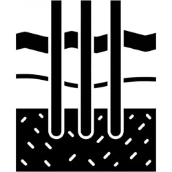
Compaction grouting injects a stiff, low-mobility mortar (typically slump 1 to 3 inches) into loose granular soils, where the grout forms an expanding bulb that displaces the surrounding ground rather than permeating it. Each injection bulb measures roughly 12 to 36 inches across and increases the relative density of the surrounding soil through controlled volumetric expansion. The method is the standard remediation for sinkhole repair in karst terrain, for densifying loose fill beneath settled slabs and shallow foundations, and for stabilizing the ground around utility installations and pipeline crossings. Injection pressures at the packer typically run 100 to 600 psi, staged bottom-up in 1 to 2 foot lifts. Surface monitoring is essential, since uncontrolled pressure can cause heave or distress to nearby structures.

Type 02

Permeation Grouting

Permeation grouting injects low-viscosity grout (microfine cement, sodium silicate, or polyurethane resin) into the existing pore network of granular soil at pressures deliberately kept below the in-situ minor principal stress. The goal is to fill the pores without disturbing soil structure, cementing the treated mass into a soft sandstone with substantially improved shear strength and substantially reduced permeability. The method works well in clean medium sands and gravels where pore openings exceed three times the largest grout particle, and fails in finer soils where particles bridge at the injection face. Permeation grouting is the standard tool for water cutoff in dam abutments, for stabilizing soils ahead of an advancing tunnel face, and for pre-treating granular ground before excavation in sensitive urban sites.

Type 03

Fracture and Compensation Grouting

Fracture grouting deliberately drives injection pressure above the in-situ minor principal stress so that the grout propagates as a thin sheet along bedding planes, joints, or weak interfaces in the host ground. The technique is delivered through TAM sleeve-port pipes installed in arrays beneath or alongside the structure to be protected, and is the dominant tool for compensation grouting on urban tunnel projects, where the sleeve-port array is used to inject above an advancing TBM and counteract surface settlement in real time. Compensation grouting is documented on major projects from the London Jubilee Line Extension to the Boston Central Artery, and is also used to controllably re-level historic buildings that have settled differentially. Pressure and volume control are critical, since the same mechanism that lifts a structure can heave or fracture it if poorly executed.

Type 04

Chemical Grouting

Chemical grouting uses reactive solutions, including sodium silicate, polyurethane, acrylate, and acrylamide, that gel or polymerize after injection to form a treated zone in the soil pore water. Because the active reagents are true solutions rather than particulate suspensions, chemical grouts can penetrate fine sands and silts that exclude even microfine cement, making them the only viable injection method for water cutoff in fine-grained ground. Polyurethane resins are particularly common for emergency leak control in sewer manholes, dam galleries, and basement walls, where the resin reacts with infiltrating water and expands twenty to thirty times its liquid volume to form a closed-cell foam barrier. Acrylate and sodium silicate gels are used for permanent treatment of fine soils where set time and gel strength can be tuned across a wide range to suit the application.

Side By Side

Pressure Grouting vs Other Ground Treatment Options

VS

Compaction Grouting vs Permeation Grouting

The defining distinction is displacement versus replacement. Compaction grouting moves soil grains closer through a controlled volumetric expansion of low-mobility grout, increasing relative density without filling the pore network. Permeation grouting leaves the grain structure undisturbed and fills the existing pores with low-viscosity grout, cementing the soil into a soft sandstone. Soil gradation drives the choice. Compaction grouting works in loose sands and silty sands of essentially any grain size, since the mechanism does not depend on grout permeating the matrix. Permeation grouting requires that the soil pore openings be at least three times the largest grout particle, which restricts cement-based permeation work to clean medium sands and coarser. Compaction grouting is preferred when the goal is to increase bearing capacity or treat a settled structure; permeation grouting is preferred when the goal is water cutoff or pre-excavation stabilization in granular ground.

VS

Pressure Grouting vs Excavate and Replace

The choice between pressure grouting and conventional excavate-and-replace is generally driven by access and depth. At shallow depths above six to eight feet with open access and no overlying structure, excavate-and-replace is typically the lower-cost solution and provides direct visual verification of the work. As depth increases, the volume of excavation and select backfill grows geometrically while grouting cost grows roughly linearly with hole depth, so beyond fifteen to twenty feet pressure grouting is almost always cheaper. Beneath an existing building or roadway, pressure grouting is often the only feasible option, since the structure cannot be undermined. The trade-off is verification: excavate-and-replace is observed in the open trench, while grouting effectiveness must be confirmed indirectly through pre- and post-treatment water testing, coring, instrumented load tests, or geophysical methods.

VS

Pressure Grouting vs Jet Grouting

Pressure grouting and jet grouting are sometimes grouped together but use fundamentally different mechanisms. Conventional pressure grouting injects grout into the existing pore structure or fractures of the host ground, with the resulting treated zone defined by where the grout was able to flow. Jet grouting uses a high-velocity grout jet (sometimes augmented with a coaxial air shroud and a separate water jet) to physically erode the soil structure and remix the spoil with grout, forming a soilcrete column of defined geometry. Jet grouting produces a controlled column diameter from two to ten feet that can be designed to meet a specific structural requirement, while pressure grouting produces an irregular treated zone whose extent must be verified after the fact. Jet grouting commands a higher cost per linear foot but is preferred where the geometry of the treated zone must be guaranteed, for example to form a continuous cutoff wall or to underpin a foundation in soil that will not accept conventional pressure grouting.

Not sure which system fits? We'll walk through the tradeoffs for your site conditions.

Talk Through Your Options
Where It Fits

Common Applications and Project Types

Dam foundation grouting is the historical anchor application and remains the largest single market for pressure grouting in US practice. Curtain grouting injects a vertical zone of grouted rock through the foundation to reduce seepage; consolidation grouting fills near-surface fractures at the rock-concrete interface to improve uplift resistance; both are routinely specified by the US Army Corps of Engineers and the Bureau of Reclamation for major embankment and concrete dams. Tunnel pre-grouting through probe holes ahead of the face controls water inflow in fractured rock and consolidates weak zones, while compensation grouting from sleeve-port arrays prevents settlement above advancing TBMs in urban tunnels. Foundation underpinning by compaction grouting is standard practice for sinkhole repair in karst regions including Florida, central Pennsylvania, and the Tennessee Valley, and pairs well with micropile underpinning when load transfer through the treated zone is required. Mine void filling and abandoned-utility grouting prevent collapse propagation, and grouting is often specified to seal water pathways behind horizontal drains or to pre-treat ground before soil nailing walls in difficult conditions. Owners selecting a grouting contractor should confirm that crews carry the specific instrumentation and grout-mixing equipment that the project subtype demands, since means and methods vary materially across compaction, permeation, fracture, and chemical work.

Filling voids or sinkholes
Slope stabilization
Underpinning foundations
Sealing water pathways in fractured rock
Increasing bearing capacity
Mitigating settlement or ground loss
Benefits

Key Advantages

In-Situ Treatment

Improves ground properties without excavation, ideal for sites with existing structures or access constraints.

Water Control

Seals fractures and voids that allow water infiltration, protecting structures and improving stability.

Void Filling

Addresses sinkholes, abandoned utilities, and subsurface voids that threaten surface structures.

Versatile Application

Multiple grout types and injection methods allow treatment of diverse ground conditions.

Immediate Results

Ground improvement is achieved during injection; results can be verified immediately.

Engineering

Technical Considerations

Soil/Rock Conditions

Grout type and injection method selected based on soil/rock permeability. Fine soils require chemical or microfine grouts; coarse soils accept cement grout.

Groundwater

Grouting can seal water pathways but must account for groundwater flow during injection. Water testing verifies treatment effectiveness.

Load Capacity

Compaction grouting densifies loose soils to increase bearing capacity. Design loads verified through testing.

Spacing

Hole spacing depends on grout travel distance and treatment objectives. Typical grids range from 3-10 ft.

Installation Method

Staged injection from bottom-up controls grout placement. Pressure monitoring prevents hydraulic fracturing or unintended ground displacement.

Equipment Used

  • Drill rigs for hole installation
  • Grout mixing and pumping plants
  • Mechanical or inflatable packers
  • Pressure gauges and flow meters
  • Monitoring equipment

Limitations

  • Grout travel unpredictable in highly fractured rock
  • Pressure limits required to prevent heave
  • Temperature affects cure time
  • May require multiple injection stages

Technical Specifications

Grout Types
Cement / Microfine / Chemical
Pressure
10 to 200+ psi
Hole Spacing
3 ft to 10 ft grid
Applications
Permeation / Compaction / Fracture
Codes And References

Engineering Standards and References

FHWA

NHI-06-019 / 06-020

Ground Improvement Methods Reference Manual

The two-volume FHWA practitioner manual covering grouting subtypes, design procedures, construction QC, and verification testing. Cited by state DOTs for ground improvement specifications on transportation projects.

USACE

EM 1110-2-3506

Grouting Technology Engineer Manual

Army Corps of Engineers manual covering rock and soil grouting, with detailed design and execution requirements for dam foundation curtain and consolidation grouting. Referenced extensively by the Bureau of Reclamation.

ASCE

Geo-Institute

Grouting Committee Specifications

The ASCE Geo-Institute Grouting Committee maintains the Glossary of Grouting Terminology and publishes the Grouting Geotechnical Special Publication series, with GSP 288 Grouting 2017 being the most recent conference proceedings.

Expertise

Why Choose Rock Supremacy for Pressure Grouting

Specialized Crews

Our grouting teams have extensive experience with controlled pressure injection in varied geological settings.

Field Instrumentation

Real-time pressure and flow monitoring ensures treatment effectiveness and prevents ground damage.

Multiple Grout Types

We select cement, microfine, or chemical grouts based on ground conditions and project objectives.

Verification Testing

Water testing, coring, and monitoring confirm treatment effectiveness before project completion.

Single-Source Delivery

Grouting is paired with drainage, anchoring, and structural reinforcement so one specialty contractor handles both ground improvement and load transfer.

Questions

Pressure Grouting FAQ

Pressure grouting is the controlled injection of fluid grout, typically a cement, microfine, or chemical mix, into soil pores, rock fractures, or open subsurface voids to alter the engineering behavior of the host ground in place. The method is a family of techniques rather than a single procedure, with compaction, permeation, fracture, and chemical grouting each driven by a different mechanism and selected for a different range of host ground. Pressure grouting is the standard tool for dam foundation curtains, tunnel pre-grouting and compensation, sinkhole and karst remediation, foundation underpinning by compaction injection, and water cutoff in fractured rock or fine soils.
Compaction grouting is a pressure grouting subtype that injects a stiff, low-mobility mortar (typically slump 1 to 3 inches) into loose granular soil. The grout does not permeate the soil pores. Instead, it forms an expanding bulb that displaces the surrounding ground radially, increasing relative density and bearing capacity through controlled volumetric expansion. Each bulb measures roughly 12 to 36 inches across, and injection pressures at the packer typically run 100 to 600 psi, staged bottom-up in 1 to 2 foot lifts. Compaction grouting is the standard remediation for sinkhole repair in karst terrain and for densifying loose fill beneath settled slabs and shallow foundations.
Permeation grouting injects low-viscosity grout (microfine cement, sodium silicate, or polyurethane resin) into the existing pore network of granular soil at pressures deliberately kept below the in-situ minor principal stress. The goal is to fill the pores without disturbing soil structure, cementing the treated mass into a soft sandstone with substantially improved shear strength and substantially reduced permeability. The method works well in clean medium sands and gravels where pore openings exceed three times the largest grout particle, and fails in finer soils where particles bridge at the injection face. Permeation grouting is widely used for water cutoff in dam abutments and for stabilizing soils ahead of an advancing tunnel face.
Chemical grouting uses reactive solutions including sodium silicate, polyurethane, acrylate, and acrylamide that gel or polymerize after injection to form a treated zone in the soil pore water. Because the active reagents are true solutions rather than particulate suspensions, chemical grouts penetrate fine sands and silts that exclude even microfine cement, making them the only viable injection method for water cutoff in fine-grained ground. Polyurethane resins are particularly common for emergency leak control in sewer manholes, dam galleries, and basement walls, where the resin reacts with infiltrating water and expands twenty to thirty times its liquid volume to form a closed-cell foam barrier.
The defining distinction is displacement versus replacement. Compaction grouting moves soil grains closer through a controlled volumetric expansion of stiff low-mobility grout, increasing relative density without filling the pore network. Permeation grouting leaves the grain structure undisturbed and fills the existing pores with low-viscosity grout, cementing the soil into a soft sandstone. Soil gradation drives the choice. Compaction grouting works in loose sands and silty sands of essentially any grain size. Permeation grouting requires that pore openings exceed three times the largest grout particle, which restricts cement-based permeation work to clean medium sands and coarser. Compaction grouting is preferred for bearing capacity gains; permeation grouting is preferred for water cutoff.
The grout family is selected for the host ground. Neat cement grout works in coarse sands, gravels, and open rock fractures. Microfine cement grouts (with maximum particle sizes around 5 to 15 microns) penetrate medium sands that reject conventional cement. Sodium silicate gels and acrylate gels treat fine sands and silts. Polyurethane resins, which react with water and expand on contact, handle emergency water cutoff in any soil and are common for sewer, dam gallery, and basement leak control. Low-mobility mortar (sand, cement, and fly ash with slump 1 to 3 inches) is the compaction-grouting mix and is selected for displacement work rather than permeation.
Grout travel is controlled by injection pressure, grout viscosity, hole spacing, and staged delivery. The hole is isolated with a mechanical or inflatable packer at the treatment depth, or for staged work a tube à manchette (TAM) sleeve-port pipe is installed full-depth, with rubber sleeves at one-foot centers that allow re-injection of any interval at will. Pressure (P), flow (Q), and volume (V) are recorded continuously at the pump and compared against design refusal criteria. Grout viscosity is matched to the host ground so that it permeates rather than fractures, or vice versa, depending on the design intent.
Yes. Pressure grouting can produce surface heave, hydraulic fracture of the host ground, and distress to nearby structures if injection pressure exceeds the in-situ minor principal stress in an uncontrolled way. The risk is greatest at shallow depth, where the overburden does not provide enough confinement to resist the injection pressure. Compaction grouting and fracture-compensation grouting deliberately use displacement and controlled fracture as the working mechanism, but the operator caps pressure and volume against pre-set thresholds, monitors the surface with optical or instrumented levels in real time, and shuts off well before damage occurs. Permeation grouting is run at pressures kept deliberately below the fracture threshold to avoid the same risk.
Verification combines pre-treatment baseline measurements with post-treatment confirmation testing. Lugeon water pressure testing in rock or constant-head permeability tests in soil establish baseline hydraulic conductivity, and the same tests are re-run after grouting to confirm the design reduction. Coring through the treated zone provides direct visual confirmation that grout filled the target geometry and reached design strength. Instrumented load tests on grouted columns or grouted soil masses confirm bearing capacity gains for compaction work. For compensation grouting, surface settlement and structure tilt instruments running through the operation provide real-time verification that the design lift was achieved without overshoot.
In US practice, three primary references govern pressure grouting design and construction. The FHWA Ground Improvement Methods Reference Manual, NHI Publications 06-019 and 06-020, covers grouting subtypes, design procedures, construction QC, and verification testing for transportation projects. The US Army Corps of Engineers Engineer Manual EM 1110-2-3506, Grouting Technology, is the controlling document for dam foundation curtain and consolidation grouting and is referenced extensively by the Bureau of Reclamation. The ASCE Geo-Institute Grouting Committee maintains the Glossary of Grouting Terminology and publishes the Grouting Geotechnical Special Publication series, with GSP 288 Grouting 2017 being the most recent conference proceedings.
Testimonials

Client Testimonials

Trusted by DOTs, engineering firms, and property owners nationwide.

Contact

Deploy Us

Ready to discuss your project? Our team is standing by to assess your site conditions and develop a custom solution using Pressure Grouting and other proven techniques.

Emergency (24/7)

(541) 383-7625

Bidding & Estimates

Info@RockSupremacy.com

Headquarters

Western Division (HQ)
65147 N Hwy 97
Bend, OR 97701
Eastern Division
915 Millennium Ct
Blountville, TN 37617

Licensed in CO, UT, WY, ID, MT, CA, WA, OR, TN, VA

Request Consultation