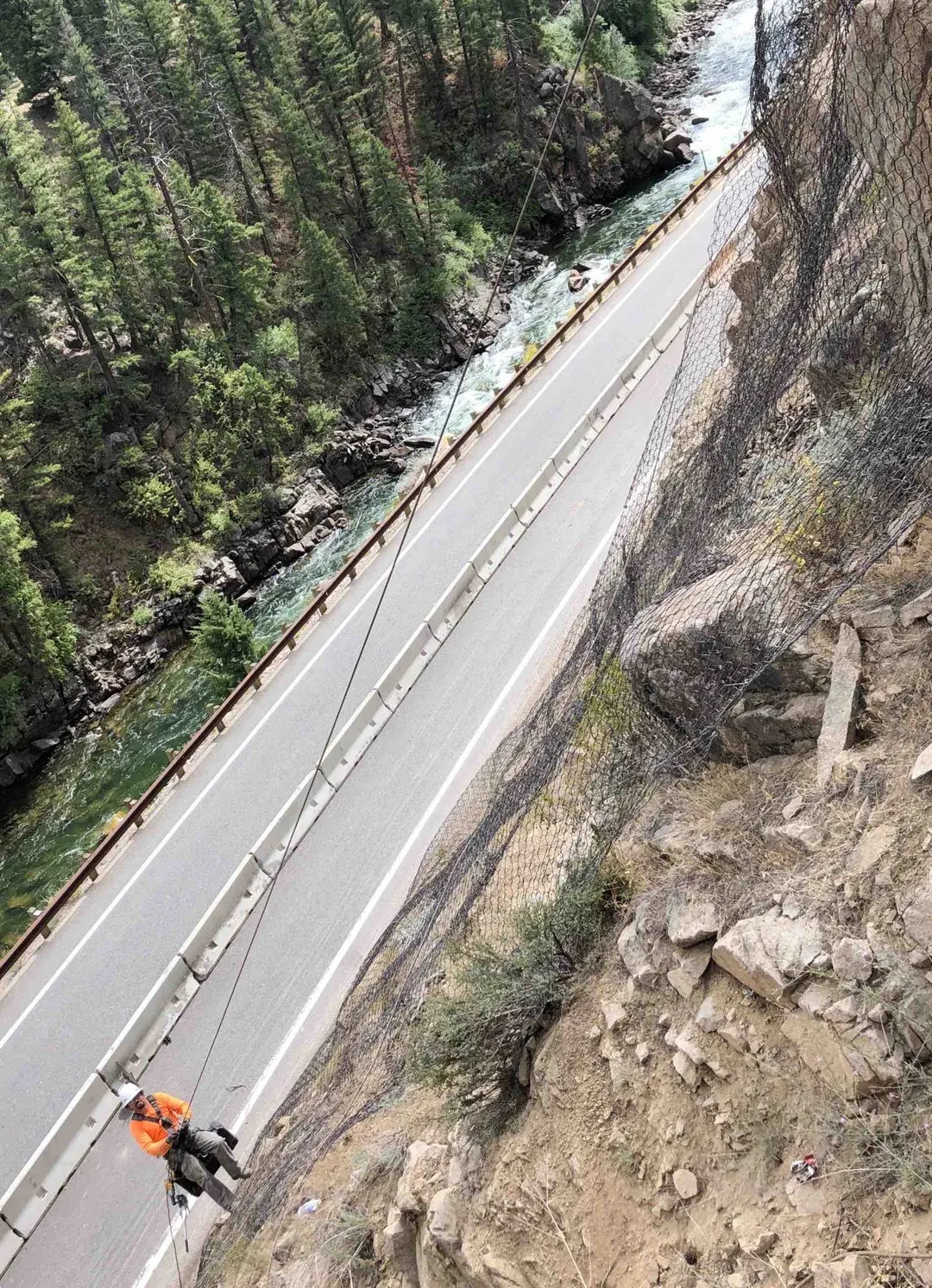
Slope failure under saturated conditions is a balance between driving forces (gravity acting on the soil mass plus the weight of pore water) and resisting forces (effective stress between soil grains plus any structural reinforcement). High pore pressure reduces effective stress, which suppresses shear strength, which lowers the factor of safety against sliding. The horizontal drain attacks this directly. A track-mounted, skid-mounted, or rope-access drill rig collars a hole at the slope face, advances a borehole 50 to 500 plus ft into the slope at 2 to 10 degrees above horizontal, and the crew installs a 2 to 4 inch slotted or perforated PVC or HDPE casing with a geotextile filter sock or graded sand pack on the up-hole portion to prevent fines migration into the drain.
Once installed, water enters the casing through the slot perforations along the saturated portion of the drain, flows downhill by gravity through the pipe, and discharges at the slope face. There are no pumps, no power, no moving parts, drainage continues 24 hours a day for the design life of the system. The piezometric head within the slope mass drops as the drain field comes online, typically over weeks to months, and the soil mass consolidates as pore pressure dissipates. On a multi-drain installation, individual drains are spaced 25 to 100 ft laterally and arrayed in fans from common drilling pads, often combined with weep drains at any new wall facing and surface drainage to keep infiltration off the slope. Pre- and post-installation piezometer readings, the standard verification per TRB Special Report 247, confirm that the drain field has produced the design drawdown.
1
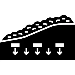
Site Investigation and Drain Field Layout
Piezometer readings, geologic mapping, and slope geometry analysis identify the saturated zone elevation and the failure surface. Drain count, length, inclination, and lateral spacing sized per TRB Special Report 247 and FHWA-NHI-08-097.
2
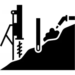
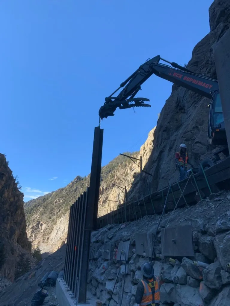
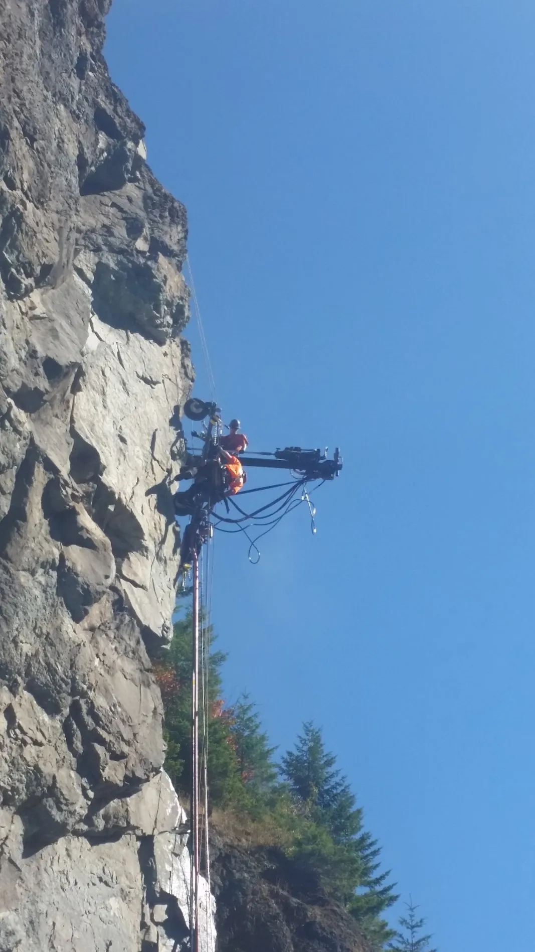
Drilling
Track-mounted, skid-mounted, or rope-access rigs collar holes at the slope face and advance 50 to 500 plus ft into the slope at 2 to 10 degree upward inclination, matched to the saturated zone geometry.
3
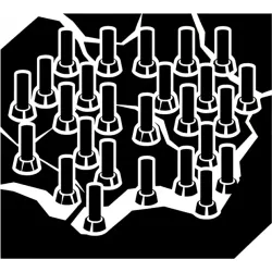
Casing and Filter Installation
2 to 4 inch slotted or perforated PVC or HDPE casing installed in the bored hole, with a geotextile filter sock or graded sand pack on the up-hole portion to prevent fines migration into the drain.
4
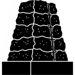
Outlet and Discharge Detailing
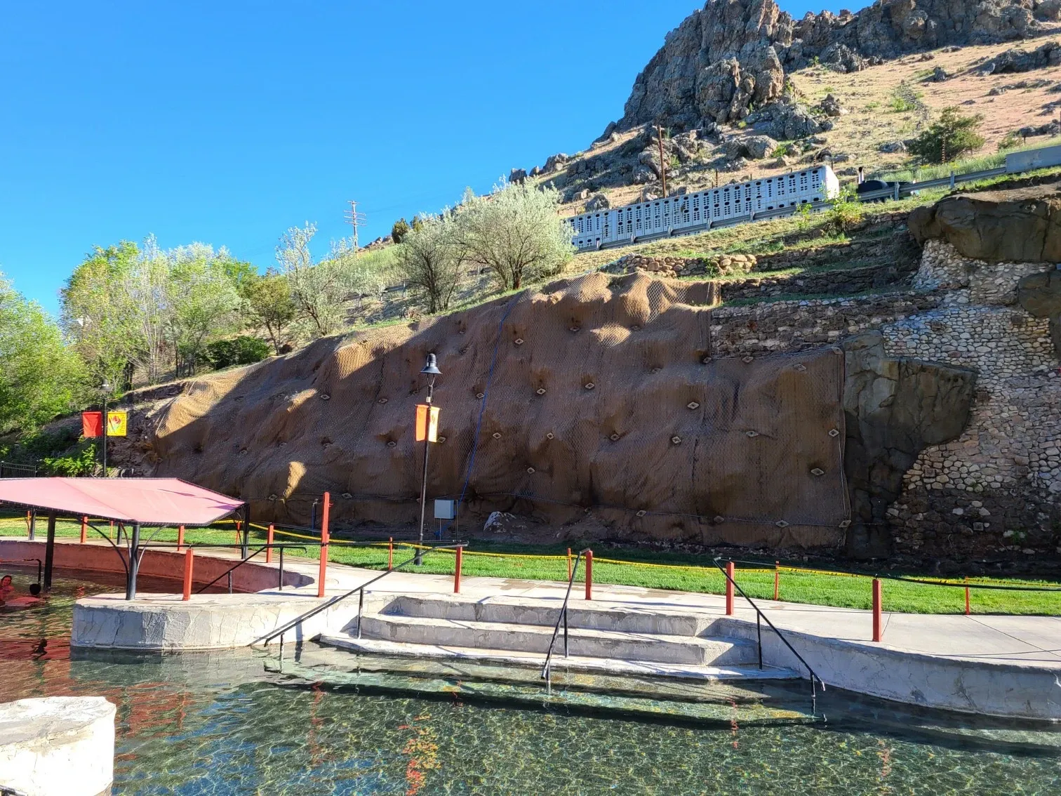
Outlet pipe daylighted at the slope face on a positive downward gradient and terminated at a splash block, rock apron, or collection trench routing flow off the slope face.
5
Drawdown Verification
Piezometer monitoring across the drain field verifies the design drawdown has been achieved. Additional drains added to the array if needed, the iterative verification approach standard in TRB Special Report 247.