Pinned Mesh Systems

Pinned Mesh Systems

Pinned mesh is the active, source-control configuration of a slope mesh system. Steel wire mesh is laid against the rock or soil face and locked at every nail or bolt intersection on a 6 to 13 ft grid, restraining loose material at the source rather than catching it after release into a toe catchment.

30-150
kN/m System Strength
6-13 ft
Nail Grid Spacing
Active
Source-Control Restraint
50+
Year Service Life
Overview

Understanding Pinned Mesh Systems

Pinned mesh is the active, source-control configuration of a slope mesh system. Steel wire mesh is laid against the rock or soil face and locked at every nail or bolt intersection on a 6 to 13 ft grid, transferring detached or sliding material into the anchorage rather than letting it travel down the slope. The configuration is the active counterpart to a draped arrangement where the same mesh hangs from a single row of crest anchors and gravity-tensions against the face.

On tall highway rock cuts, the two configurations are routinely paired, draped mesh handles the persistent upper-slope freeze-thaw release while pinned sections actively restrain blocks on the lower face adjacent to the travel lane, where catchment ditch width is too narrow to accept a drapery-only design. Where the design block exceeds the working range of woven mesh, the same pinned configuration is built with wire rope netting on a heavier-duty anchor grid, holding multi-ton boulders in place rather than letting them release to a downstream catchment.

Mesh selection within a pinned configuration spans a wire-grade range. Double-twisted hexagonal mesh under ASTM A975 works for sub-ton applications, but on slopes where nail loads or punching capacity at the bolt head govern the design, TECCO high-tensile diamond mesh with pressed spike plates is specified. The plate teeth engage multiple wire intersections around each nail rather than only the four wires the bolt passes through, which is what unlocks the active pre-tensioning that distinguishes TECCO from passive containment mesh.

What Is Pinned Mesh?

Pinned mesh is the active, source-control configuration of a slope mesh system. Steel wire mesh is laid against the rock or soil face and locked at every nail or bolt intersection on a 6 to 13 ft grid, transferring detached or sliding material into the anchorage at the source rather than letting it travel down the slope and into a catchment ditch at the toe. The configuration is the active counterpart to a draped mesh arrangement, in which the same mesh products hang from crest anchors only.

US practice spans three mesh product families in the pinned configuration. Double-twisted hexagonal mesh under ASTM A975, system capacity 30 to 50 kN/m, runs in lower-load applications. High-tensile diamond mesh, Geobrugg TECCO and equivalents at 1,770 N/mm² wire grade and up to 150 kN/m system capacity, runs in the dominant DOT and mining case. Cable-net mesh, Geobrugg SPIDER and equivalents on 200 to 300 mm patterns, runs when the design block exceeds the woven-mesh working range. Anchorage is sized under AASHTO LRFD §11.12 for soil and weathered rock and the FHWA Soil Nail Walls Reference Manual (NHI-14-007). Mesh capacity, plate spacing, and pre-tension are dimensioned by Geobrugg's RUVOLUM analysis. Slopes are prioritized for active-mesh treatment under the FHWA Rockfall Hazard Rating System (FHWA-OR-EG-90-01).

Key Benefits

  • Active source-control restraint, not passive containment
  • Removes the dependency on a sized toe catchment ditch
  • Configurable across hexagonal, high-tensile diamond, and cable-net mesh products
  • Compatible with shotcrete facing for weathering protection
  • 50+ year service life with galvanized wire and grouted anchors
The Engineering

How Pinned Mesh Works

How the system carries load in service, and how we build it on site.

Construction is anchorage-first, mesh-second. Crews scale the slope, then drill and grout a pattern of rock bolts on rock or soil nails on weathered rock and soil at 6 to 13 ft on-center, sized by RUVOLUM and the governing nail standard. Mesh panels are unrolled from the crest down, overlapped at the seams and laced together with high-strength clips, and locked at each nail head with a pressed plate. On hexagonal mesh systems the plate is a flat washer or claw plate. On TECCO and other high-tensile diamond mesh systems, the plate is a pressed spike plate that engages multiple wire intersections around the bolt and is torqued to a design pre-tension before any block release, converting the system from passive containment into active restraint.

Load path in service runs detached block or sliding mass into the mesh, mesh into plate, plate into the nail, and nail into competent ground. Three modes govern the design. Shallow-failure kinematics define the wedge that can slide between adjacent nails. Mesh bulging capacity bounds how much that wedge can deform the mesh outward before tensile failure. Punching capacity at the plate bounds how much nail load can be transferred through the plate-to-mesh connection without local failure at the bolt head. RUVOLUM verifies all three modes for the project geometry, while AASHTO LRFD §11.12 and FHWA NHI-14-007 govern nail pull-out and global stability. Production nails are pull-tested per ASTM D4435 to verify the as-built capacity before mesh deployment.

1

Scaling & Surface Prep

Remove loose blocks and overhangs, trim vegetation, and prepare the slope face for full mesh contact.

2

Nail Pattern Drilling

Drill and grout rock bolts or soil nails on the RUVOLUM-sized grid, typically 6 to 13 ft on-center.

3

Mesh Deployment

Unroll mesh panels from the crest down, overlap seams, and lace adjacent panels with high-strength clips.

4

Plate Installation & Pre-Tensioning

Set a flat washer, claw plate, or pressed spike plate at every nail head and torque to design pre-tension.

5

Pull-Test Verification

Pull-test production nails per ASTM D4435 to verify as-built capacity against AASHTO LRFD §11.12 and RUVOLUM design loads.

System Variants

Pinned Mesh Product Variants

Type 01

Hexagonal Mesh on a Bolt Grid

The lower-end configuration, double-twisted hexagonal steel wire mesh under ASTM A975 anchored to a grid of rock bolts with flat washers or claw plates. System capacity runs 30 to 50 kN/m, sufficient for sub-ton block release in low-rate applications and for slopes where the design block falls within the hex working range. Hex mesh transfers nail load only through the four wires the bolt passes through, which is what caps its capacity below the high-tensile diamond products and limits its use on punching-controlled designs.

Type 02

High-Tensile Diamond Mesh with Spike Plate

The dominant US pinned-mesh installation. TECCO and equivalent diamond mesh products run at 1,770 N/mm² wire grade on an 83 × 143 mm pattern, with system capacities to 150 kN/m for the standard G65/3 product. The defining hardware is the pressed spike plate, which engages multiple diamond intersections around each nail rather than only the four wires the bolt passes through, distributing the nail load into a larger patch of mesh. The plates can be torqued to pre-load the mesh before any block release, converting the system into active source-control restraint and unlocking the higher capacity of the high-tensile wire grade.

Type 03

Cable-Net Mesh in Pinned Configuration

When the design block exceeds the working range of woven mesh, the same pinned anchorage geometry is built with wire rope netting. Helically wound 8 to 12 mm steel cables on a 200 to 300 mm grid carry block-release loads measured in tens of tons per panel, and the cable-net product family is the correct tool for multi-ton boulder containment on critical infrastructure slopes. Anchorage is heavier-duty than for woven mesh, with bolt or nail capacity sized to the larger design block and edge cables used to distribute load across the panel.

Side By Side

Pinned Mesh vs Other Slope Systems

VS

Pinned vs Draped Mesh

The fundamental axis is active restraint versus passive containment. Pinned mesh is anchored across the entire slope on a 6 to 13 ft nail or bolt grid, holding loose material in place at the source. Draped mesh hangs from a single row of crest anchors only and gravity-tensions against the face, accepting that detached blocks will travel down between the mesh and the slope into a catchment area at the toe. Pinned is preferred where rocks must not move at all, near roadways without adequate catchment, beneath buildings, and at portal mouths. Drape is preferred on tall slopes with continuous source release and an available toe-of-slope catchment, where face-anchoring the entire slope is uneconomic.

VS

Pinned Mesh vs Soil Nail Wall with Shotcrete

Pinned mesh is a containment surface tied into a nail grid, the mesh handles surface release while the nails reinforce the underlying ground. A soil nail wall with structural shotcrete is a structural retaining wall, the shotcrete face carries flexural load between nails and the wall is dimensioned to retain a verticalized cut. Pinned mesh is the right choice when the slope is stable at its as-cut angle and the work is to restrain surface-level instability or shallow-wedge release. A nailed shotcrete wall is the right choice when the cut is verticalized beyond stable angle or the design requires a structural facing, with mesh as flexible reinforcement under the shotcrete in either case.

VS

Pinned Mesh vs Rockfall Barriers

Pinned mesh restrains loose material at the source on the slope face. A rockfall barrier is a free-standing fence at or below the toe with hinged steel posts and a flexible ring or cable net rated to a specific impact energy, typically 100 to 10,000+ kJ. Pinned mesh prevents block release in the first place, barriers stop blocks that have already released and accelerated through free-fall or roll. The two are complementary on critical corridors, pinned mesh on the upper face restrains the high-rate weathering source and a barrier at the toe backstops the residual high-energy events that exceed the mesh design block.

Not sure which system fits? We'll walk through the tradeoffs for your site conditions.

Talk Through Your Options
Where It Fits

Where Pinned Mesh Fits

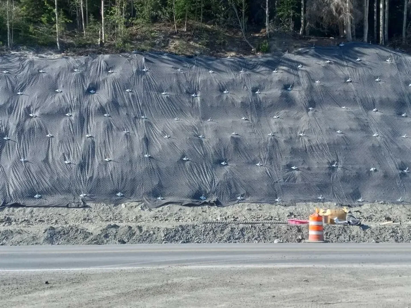
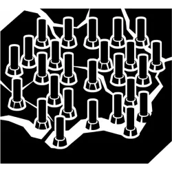
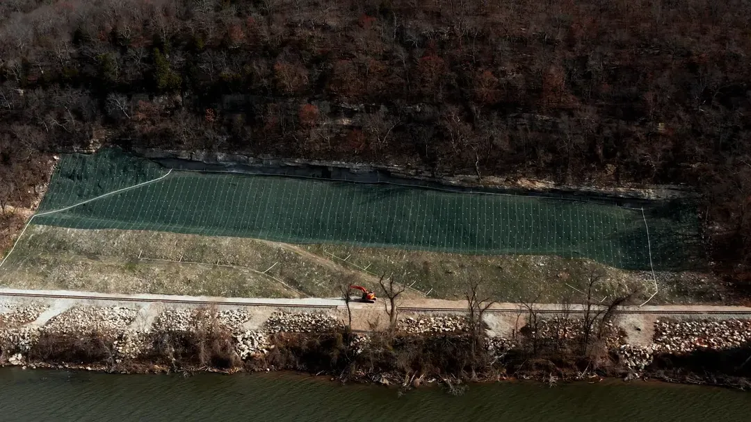
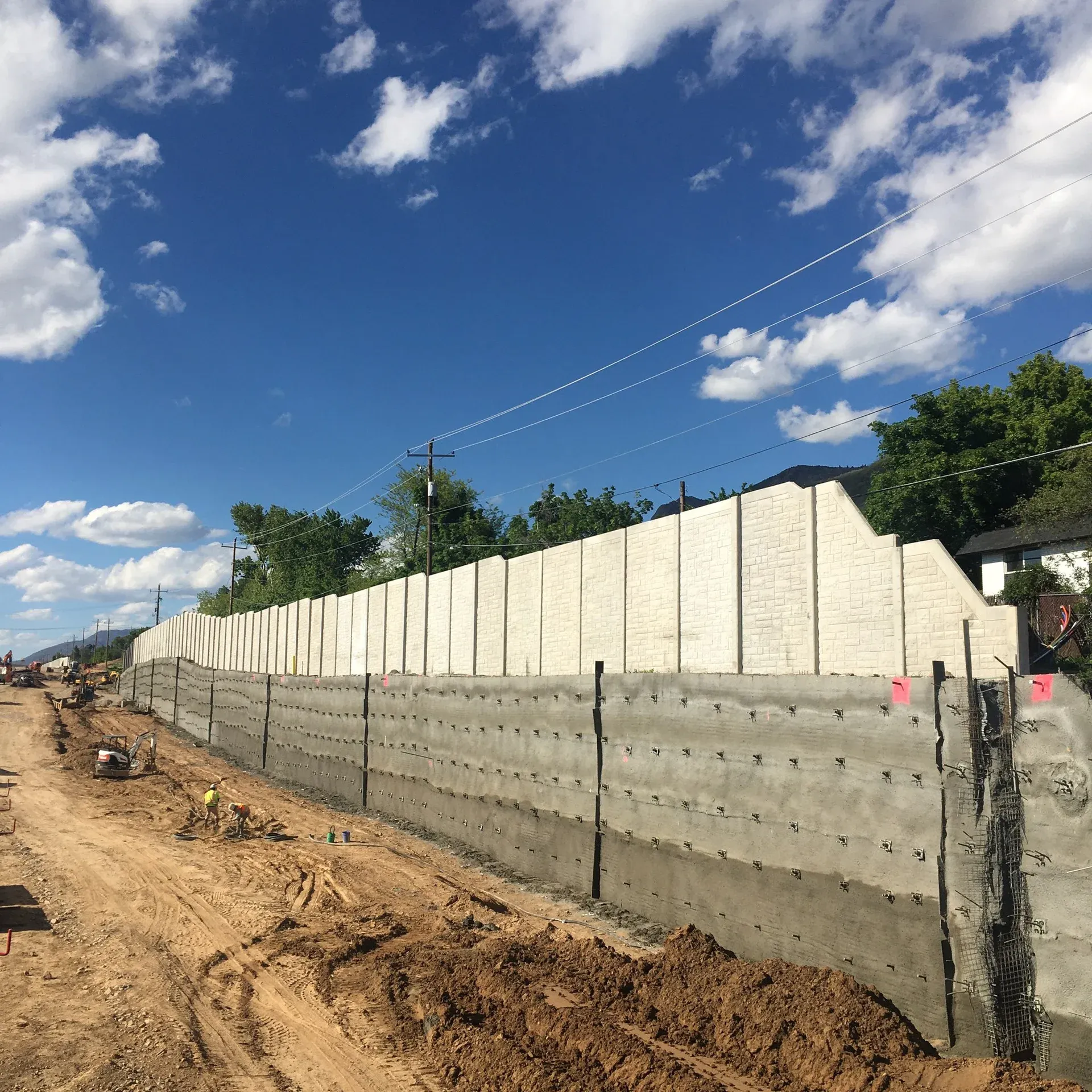
State DOT highway rock cuts with constrained catchment-ditch geometry are the dominant US application. Where alignment, right-of-way, or topography limits the toe ditch, drapery is not feasible and active restraint at the source is the only way to keep blocks off the travel lane. Pinned mesh on a soil nail or rock bolt grid sized by RUVOLUM and AASHTO LRFD §11.12 is the standard treatment for these constrained-toe corridors.

Mining highwalls under active production are the second heavy market. Crews working beneath a face require that surface release be restrained at the source rather than caught at the toe, so high-tensile pinned mesh with pre-tensioned spike plates is the routine specification on Class I metals and aggregates pits where the highwall is in long-term service.

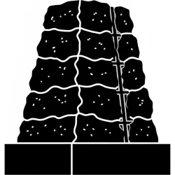
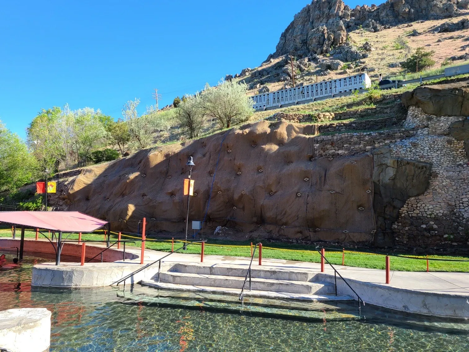
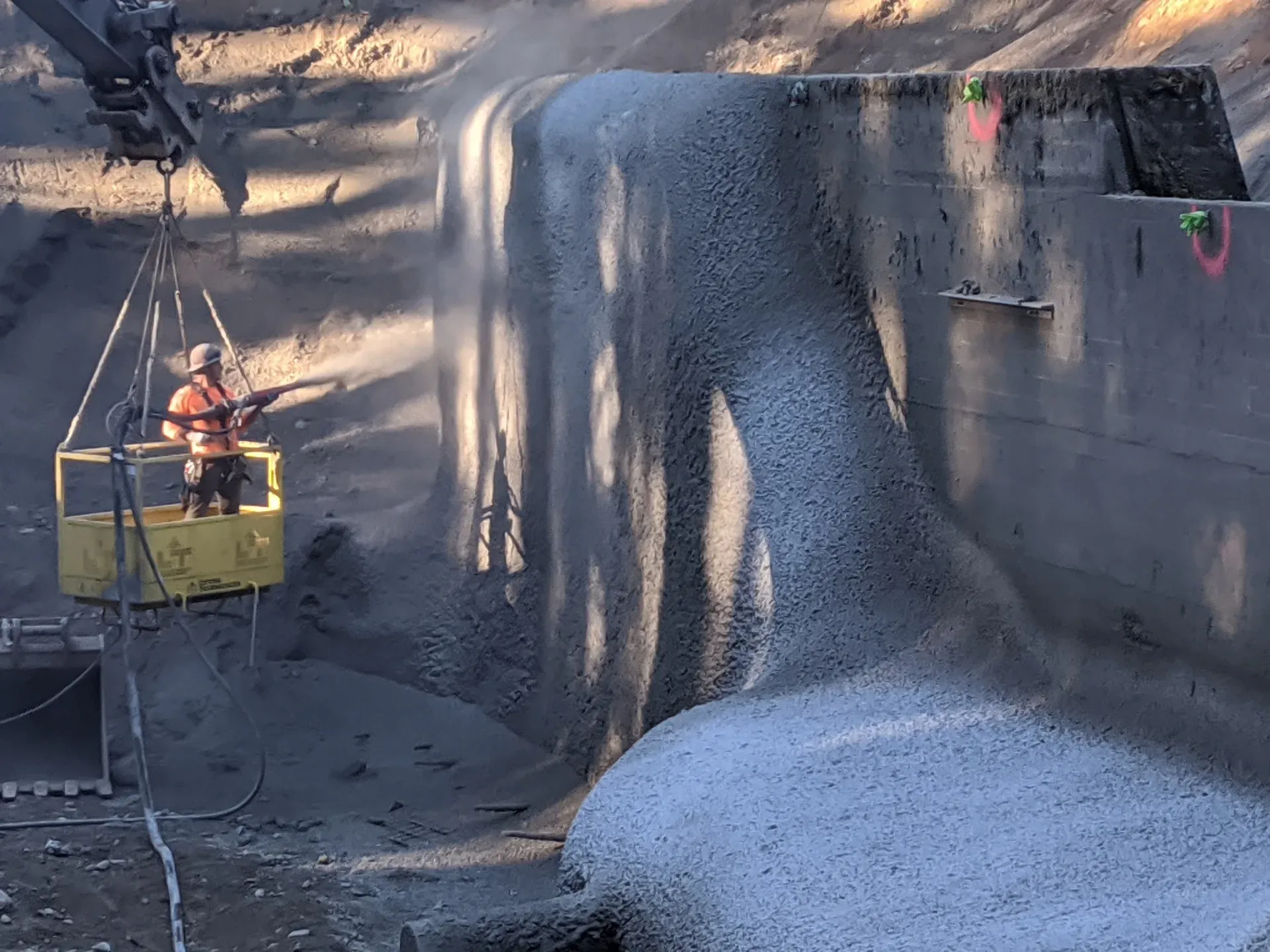
Tunnel portals and bridge abutments use pinned mesh when the slope above critical structure cannot tolerate blocks of any size releasing onto the asset. The configuration pairs naturally with structural shotcrete facing when surface weathering protection is also required, with the mesh acting as flexible reinforcement under the shotcrete shell.

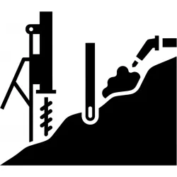
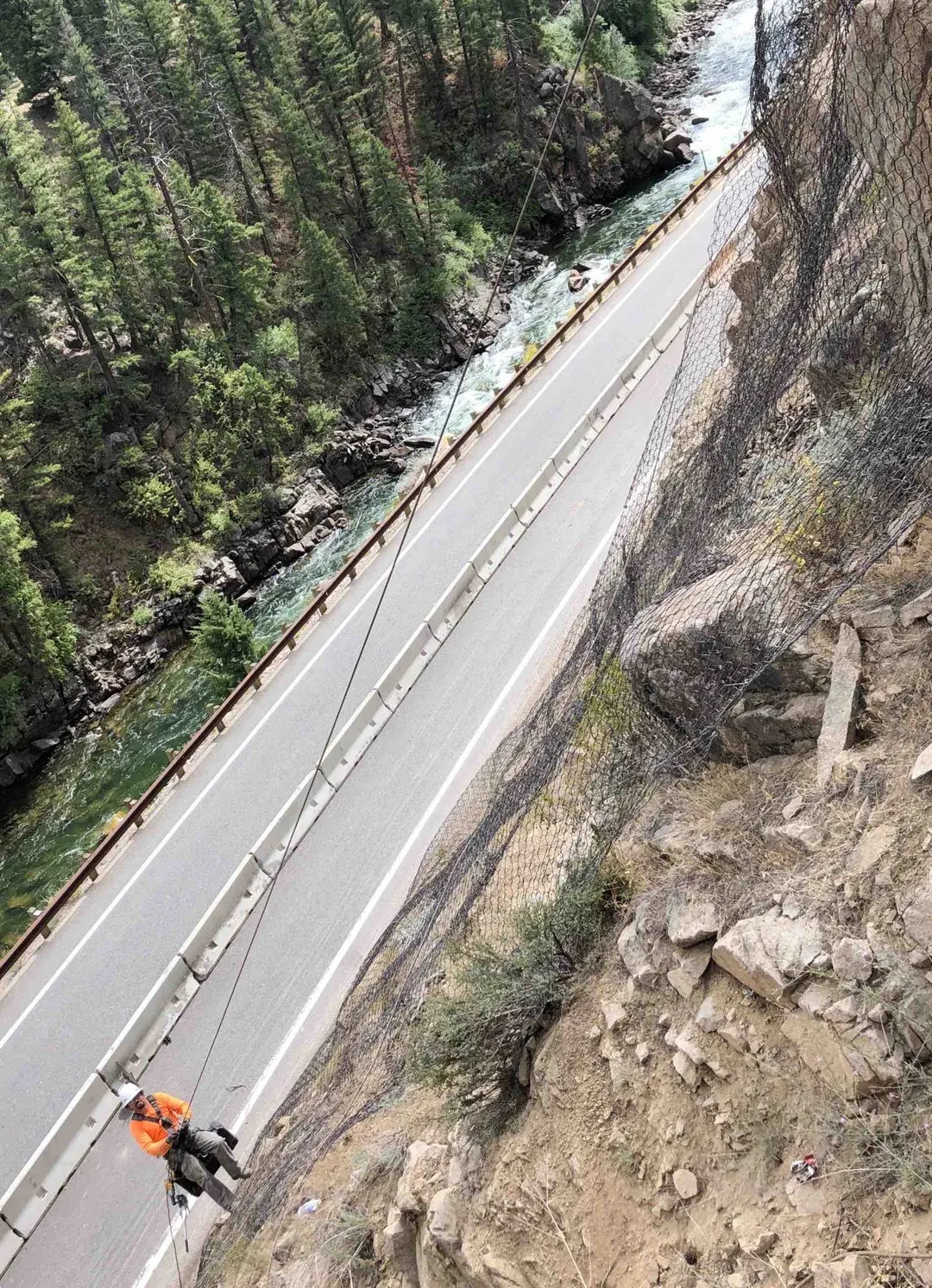
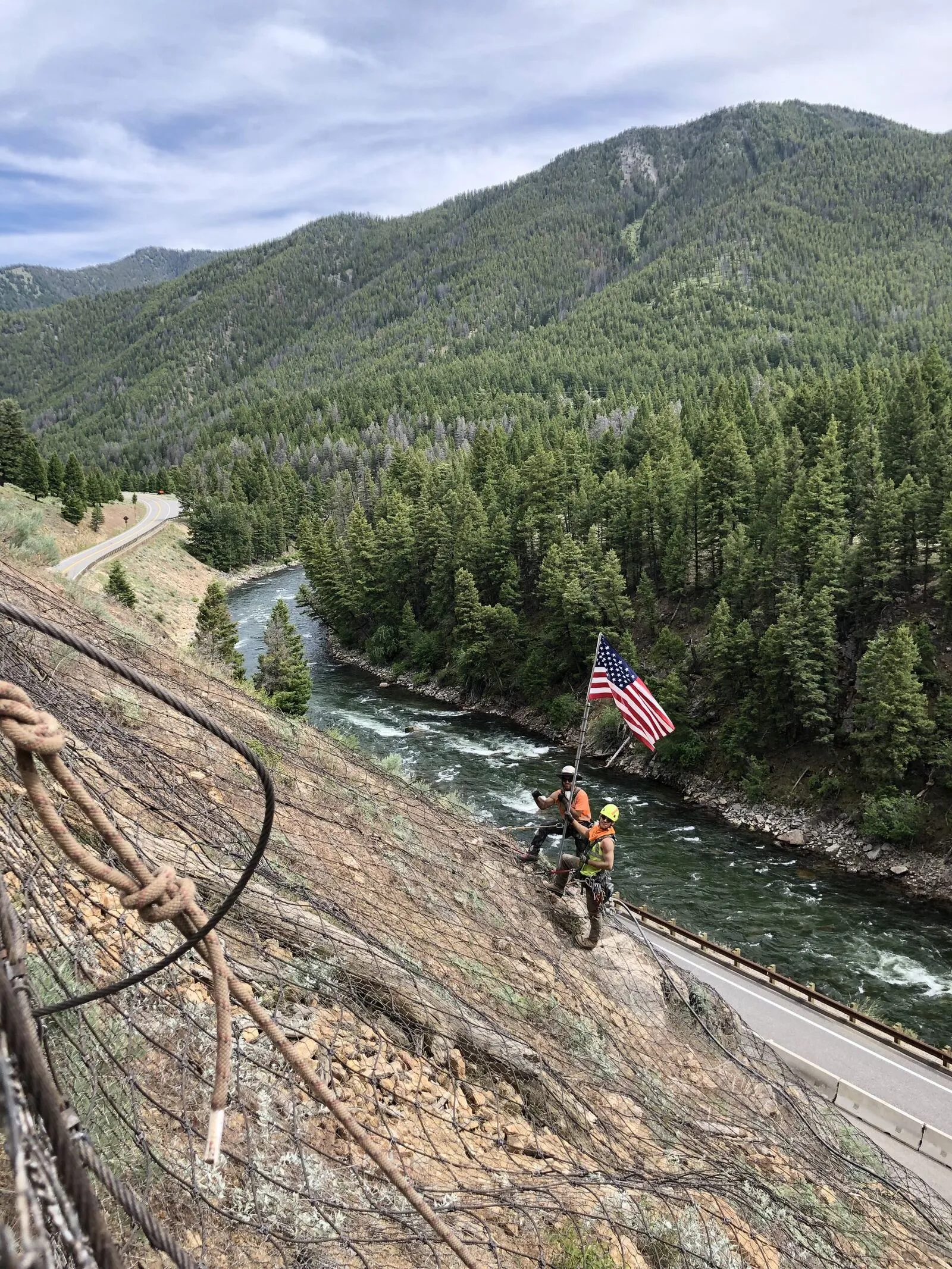
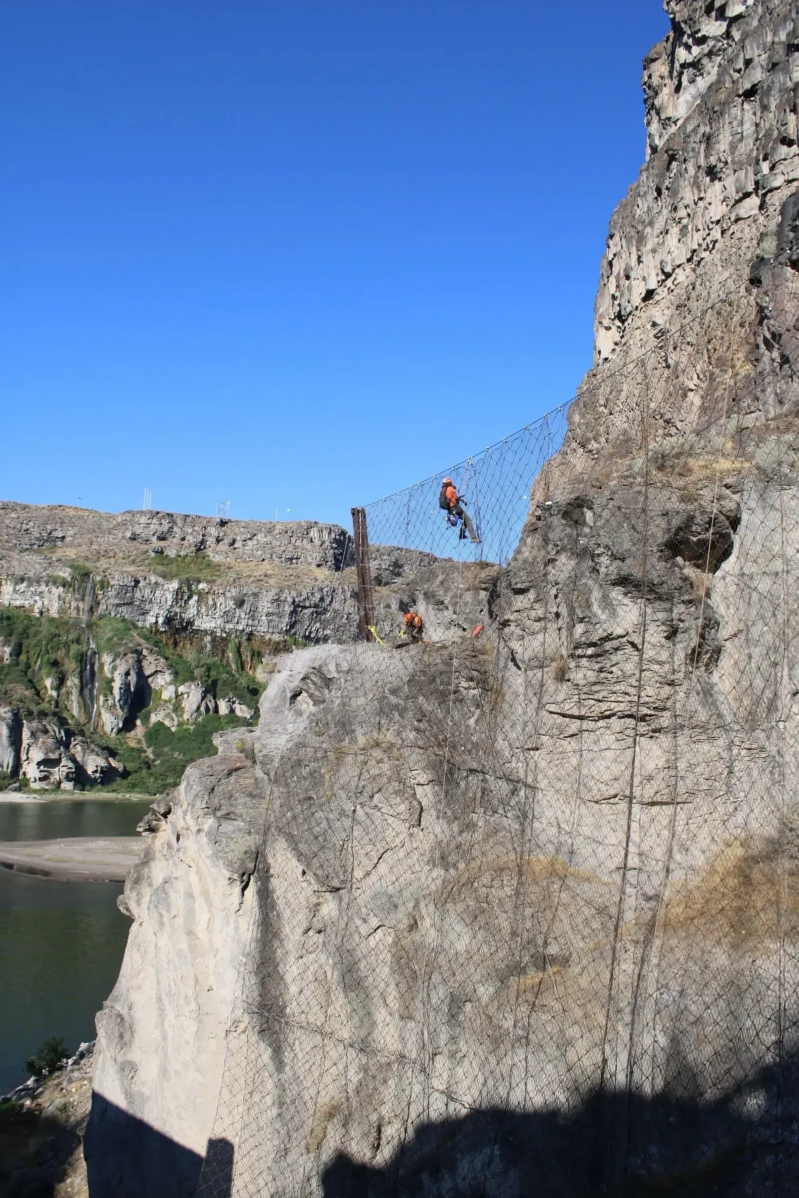
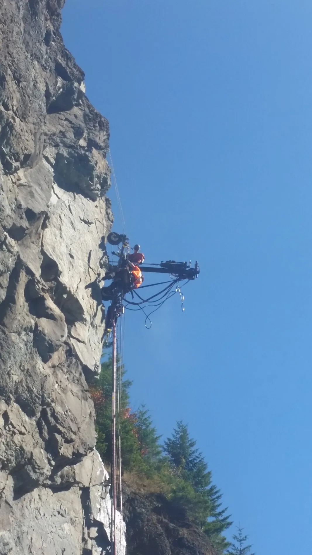
Steep, rope-access-only terrain is the fourth common case. SPRAT and IRATA crews can drill nails, hang mesh, and torque spike plates on vertical and overhanging faces where vehicle-mounted drilling is impossible, including canyon rail corridors, port rockfall sites, and remote mountain highways. The same access methods carry through to hybrid drape-and-pinned configurations on tall slopes where the upper face is draped and the lower face adjacent to infrastructure is pinned.

Highway rock cuts with constrained catchment-ditch geometry
Mining highwalls under active production
Tunnel portals and bridge abutment slopes
Critical infrastructure where blocks cannot be allowed to release
Rope-access slopes on canyon rail and port rockfall corridors
Hybrid drape-and-pinned corridors on tall highway slopes
Slope reinforcement under structural shotcrete facing
Benefits

Key Advantages

Active Source-Control Restraint

Mesh and anchor grid restrain loose material at its origin, the load path runs from block into mesh into plate into nail into ground rather than catching after release.

Configurable Across Mesh Products

The same anchorage geometry runs hexagonal mesh for sub-ton applications, high-tensile diamond mesh for the dominant DOT case, and cable-net for multi-ton blocks.

Constrained-Toe Performance

Active restraint at the source removes the dependency on a sized toe ditch, which is what drives pinned-mesh selection on highway corridors with limited right-of-way.

Shotcrete and Drainage Integration

The same nail grid carries pinned mesh, structural shotcrete reinforcement, and drainage outlets, allowing combined restraint, facing, and seepage control on a single anchorage.

Long Service Life

Class A galvanized wire mesh and cement-grouted anchors achieve 50+ years in service with periodic anchor inspection and plate retorque.

Engineering

Technical Considerations

Soil/Rock Conditions

Pinned mesh is installed on fractured rock, weathered rock, and soil slopes. Nail type, length, and spacing are sized by RUVOLUM and the governing nail standard against the controlling shallow-failure wedge for the site geology.

Groundwater

Mesh is fully permeable and does not trap water against the slope. Where seepage is concentrated, weep drains or horizontal drains are integrated through the anchor pattern to relieve pore pressure behind the mesh.

Load Capacity

System capacity is the lesser of mesh tensile capacity, plate punching capacity at the nail head, and nail pull-out capacity. RUVOLUM verifies each mode for the project loads, and production nails are pull-tested per ASTM D4435 to confirm the as-built anchorage.

Spacing

Nail grid runs 6 to 13 ft on-center depending on rock quality, expected block size, and pre-tension load. Tighter spacing is used where punching at the plate or shallow-wedge kinematics govern.

Installation Method

Mesh unrolled from crest, overlapped and laced at the seams, locked at each nail head with a flat washer, claw plate, or pressed spike plate, and pre-tensioned to design torque on high-tensile diamond systems.

Equipment Used

  • Track-mounted or rope-access drill rigs
  • Mesh handling rigging and panel deployment gear
  • Flat washers, claw plates, or pressed spike plates with lacing clips
  • Torque wrenches calibrated to design pre-tension
  • ASTM D4435 pull-test rigs for nail load verification

Limitations

  • Requires competent ground for nail anchorage
  • Higher drilling and material cost than draped systems
  • Pre-scaling required for effective mesh contact
  • Vertical and overhanging faces require rope-access installation

Technical Specifications

System Strength
30 kN/m to 150 kN/m
Nail Grid
6 ft to 13 ft on-center
Plate Type
Flat Washer / Claw Plate / Spike Plate
Mesh Products
ASTM A975 Hex / High-Tensile Diamond / Cable Net
Codes And References

Standards & References

AASHTO

LRFD §11.12

Soil Nail Wall Design

Governs the soil nail and rock bolt anchoring component of pinned mesh installations on soil and weathered rock slopes. Provides load and resistance factors, pull-out checks, and global stability requirements that pair with RUVOLUM mesh-and-plate verification on the same slope.

FHWA

NHI-14-007

Soil Nail Walls Reference Manual

The supporting reference manual for AASHTO LRFD §11.12. Defines nail length, bonded length, head detailing, pull-test protocols (ASTM D4435), and corrosion protection requirements that govern the anchorage grid behind a pinned mesh face.

Geobrugg

RUVOLUM

Manufacturer Dimensioning Method for Flexible Slope Stabilization

The published design procedure for high-tensile mesh slope-stabilization systems. Sizes mesh capacity, nail length and spacing, and pre-tension against three governing modes: shallow-wedge kinematics between nails, mesh bulging at the wedge, and spike plate punching at the nail head. Cited directly in DOT and mining specifications for pinned TECCO.

FHWA

FHWA-OR-EG-90-01

Rockfall Hazard Rating System (Pierson, Davis, Van Vickle 1990)

The state-DOT framework that drives treatment selection on rock slopes. RHRS scoring of slope geometry, block size, climate, ditch effectiveness, and historic rockfall produces the prioritization that puts active mesh systems on slopes where drapery plus catchment is insufficient.

Gallery

Our Work in Action

Expertise

Why Choose Rock Supremacy for Pinned Mesh

Configuration Across Mesh Products

Field experience installing pinned mesh in hexagonal, high-tensile diamond (TECCO), and cable-net configurations, sized to the design block and corridor geometry.

Rope-Access Capability

SPRAT/IRATA-trained technicians install pinned mesh on vertical and overhanging faces where vehicle-mounted equipment cannot work.

Integrated Anchoring

We self-perform scaling, soil nail and rock bolt drilling, mesh deployment, and plate tensioning with our own crews, no subcontractor handoffs.

Pull-Tested Anchors

Production nails and bolts are pull-tested per ASTM D4435 to verify design capacity before mesh deployment, with documentation for owner records.

Multi-Sector Capability

Pinned mesh installed for state DOTs, Class I railroads, and mining operators across the Pacific Northwest and Southeast.

Questions

Pinned Mesh Systems FAQ

Pinned mesh is the active, source-control configuration of a slope mesh system. Steel wire mesh is laid against the rock or soil face and locked at every nail or bolt intersection on a 6 to 13 ft grid, transferring detached or sliding material into the anchorage rather than letting it travel down the slope. The configuration is the active counterpart to a draped mesh arrangement, in which the same mesh hangs from a single row of crest anchors only.
Pinned mesh is anchored to the slope on a 6 to 13 ft grid of rock bolts or soil nails, actively holding loose material in place at the source. Draped mesh is anchored only at the slope crest and gravity-tensions against the rock face, accepting that blocks will detach and travel down to a catchment area at the toe. Pinned is preferred where rocks must not move at all, near roadways without adequate catchment, above buildings, and at portal mouths. Drape is preferred on tall slopes with continuous source release and an available toe catchment.
Three product families. Double-twisted hexagonal mesh under ASTM A975 (system capacity 30 to 50 kN/m) is used in lower-load applications. High-tensile diamond mesh, Geobrugg TECCO and equivalents at 1,770 N/mm² wire grade and up to 150 kN/m system capacity, is the dominant US product on DOT and mining slopes. Cable-net mesh, Geobrugg SPIDER and equivalents on a 200 to 300 mm grid, is specified when the design block exceeds the woven-mesh working range and tens of tons per panel are required.
Nail or bolt grid spacing runs 6 to 13 ft on-center, sized by RUVOLUM against rock quality designation, design block size, and pre-tension load on high-tensile diamond systems. Tighter spacing is used where punching capacity at the plate governs the design or where shallow-failure kinematics produce a small allowable wedge between nails. Hex mesh on a bolt grid typically falls in the 6 to 10 ft range, while diamond and cable-net configurations extend to the upper end of the spacing range.
Anchorage design follows AASHTO LRFD §11.12 (Soil Nail Wall Design) and the FHWA Soil Nail Walls Reference Manual (NHI-14-007), which together define nail length, bonded length, pull-out checks, global stability, and ASTM D4435 pull-test protocols. Mesh capacity, plate spacing, and pre-tension are dimensioned by Geobrugg's RUVOLUM analysis against shallow-wedge kinematics, mesh bulging, and plate punching modes. Slopes are prioritized for active-mesh treatment under the FHWA Rockfall Hazard Rating System (FHWA-OR-EG-90-01).
Yes. Pinned mesh acts as flexible reinforcement under a structural shotcrete shell, with the same nail or bolt grid carrying both. The mesh distributes shrinkage and impact stresses in the shotcrete while continuing to carry block-release load through the plates and into the anchorage. The hybrid is common on tunnel portal slopes, urban cut walls, and any face where surface weathering protection is required alongside active restraint.
Production nails and bolts are pull-tested per ASTM D4435 to verify the as-built anchorage against the design pull-out capacity from AASHTO LRFD §11.12 and RUVOLUM. A defined fraction of production nails is tested at full design load, with proof and creep tests performed on a smaller percentage. Test results are documented in submittals to the owner, and any nail that fails the proof test is replaced or supplemented before mesh deployment.
Production rate depends on access, drilling conditions, and mesh product. With vehicle-mounted drilling and crane or telehandler mesh deployment, crews routinely complete substantial coverage areas per shift. Rope-access-only slopes are slower because nails and mesh must be staged from the rope. The pre-tensioning step on high-tensile diamond systems adds time per nail compared to a passive-plate hex installation.
Yes. The two most common combinations are hybrid drape-and-pinned, where drapery on the upper slope transitions to pinned mesh on the lower face adjacent to a travel lane, and pinned mesh paired with a rockfall barrier at the toe to backstop high-energy events that exceed the mesh design block. Pinned mesh also pairs with horizontal drains threaded through the anchor pattern for slopes with concentrated seepage and with structural shotcrete facing for weathering protection.
Testimonials

Client Testimonials

Trusted by DOTs, engineering firms, and property owners nationwide.

Contact

Deploy Us

Ready to discuss your project? Our team is standing by to assess your site conditions and develop a custom solution using Pinned Mesh Systems and other proven techniques.

Emergency (24/7)

(541) 383-7625

Bidding & Estimates

Info@RockSupremacy.com

Headquarters

Western Division (HQ)
65147 N Hwy 97
Bend, OR 97701
Eastern Division
915 Millennium Ct
Blountville, TN 37617

Licensed in CO, UT, WY, ID, MT, CA, WA, OR, TN, VA

Request Consultation