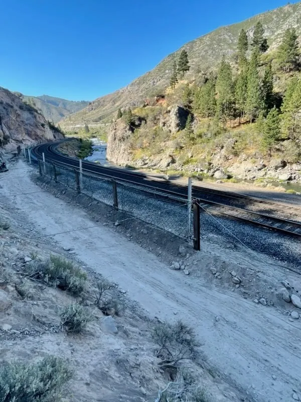
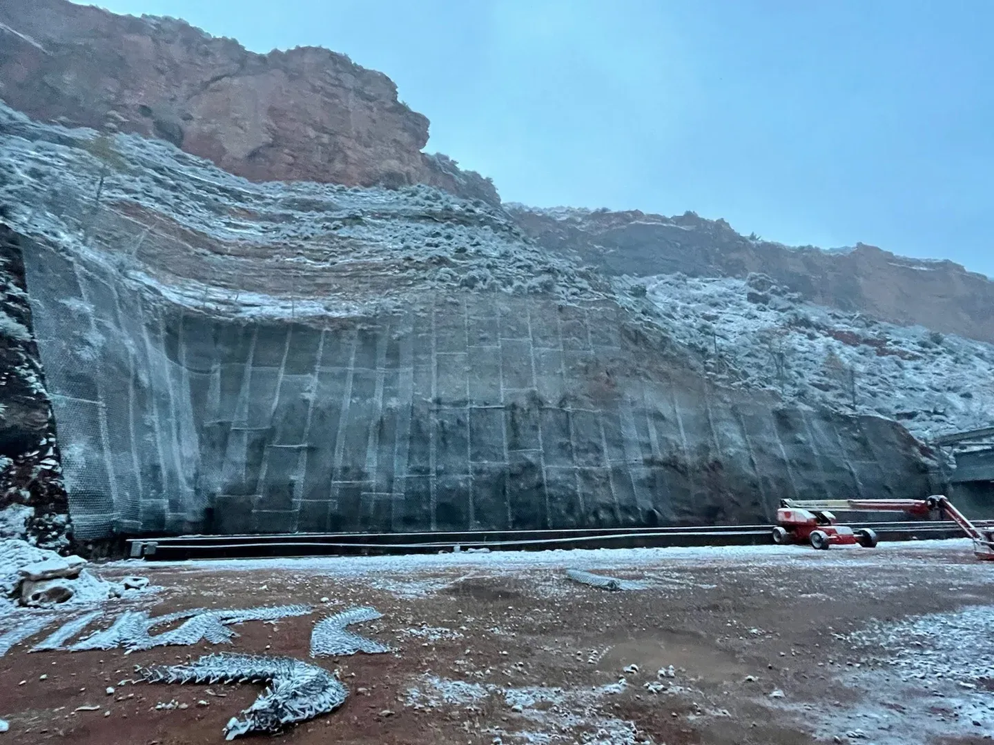
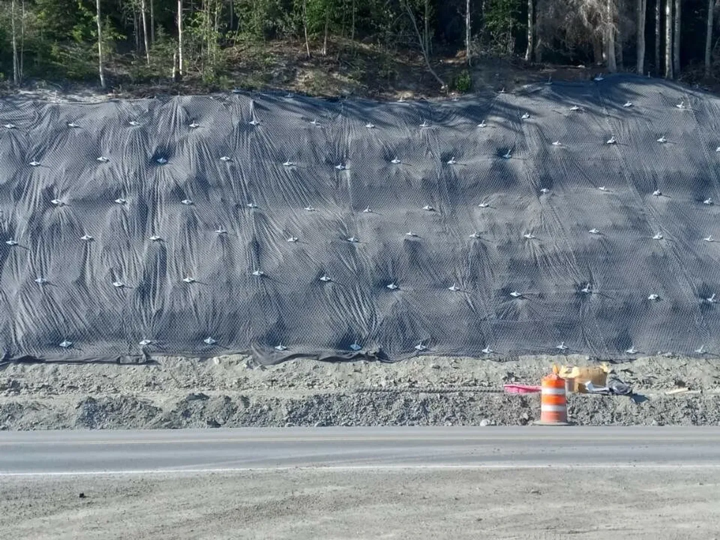
Construction is anchor-first, panel-second, with anchors sized for the heavier system load. In drape configuration, crews drill a row of crest anchors with larger-diameter threadbar (typically 1.0 to 1.5 in / 25 to 38 mm) embedded 8 to 20 ft into competent rock or soil at 10 to 30 ft on-center, with a tensioned perimeter wire rope threaded through the anchor heads to support the panel. In pinned configuration, the anchor pattern extends across the slope face, typically on a 6 to 10 ft grid of rock bolts or tieback anchors, each terminating in a heavy bearing plate that loads the cable-net intersection points directly. Cable-net panels are pre-fabricated off-site (panel sizes set by the lift capacity of the helicopter or crane on site), staged at the crest, and lifted into position. Rope-access crews then lace adjacent panels with shackles or specialized cross clips at each rope intersection along the seam line.
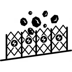
In service, the load path runs through the cable matrix into the perimeter rope and into the anchors. When a block strikes the net in drape configuration, the impact deforms the local cable matrix elastically, transfers tension into the perimeter rope along all four edges of the panel, and discharges through the perimeter into the crest and lateral edge anchors. The block decelerates as it ricochets between cable net and rock during its descent into the catchment area at the toe. In pinned configuration, the impact energy is absorbed locally between adjacent face anchors and transfers directly into the bolt grid rather than running the full panel length. In barrier configuration, the cable net is the interception element behind the post line: the block deforms the cable matrix, the deformation pulls tension into the support cables, brake elements extend through controlled friction or pipe deformation, and the residual load transfers into the foundations exactly as in a ring-net barrier. The cable-rope construction provides higher stiffness and lower elongation than woven mesh, which is why cable nets are favored where the deflection envelope behind the system is constrained.
1
Design Analysis
Rockfall trajectory modeling under FHWA RHRS sets cable diameter, grid spacing, and anchor capacity for the design block and impact energy.
2
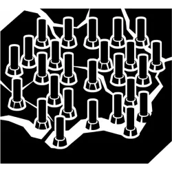
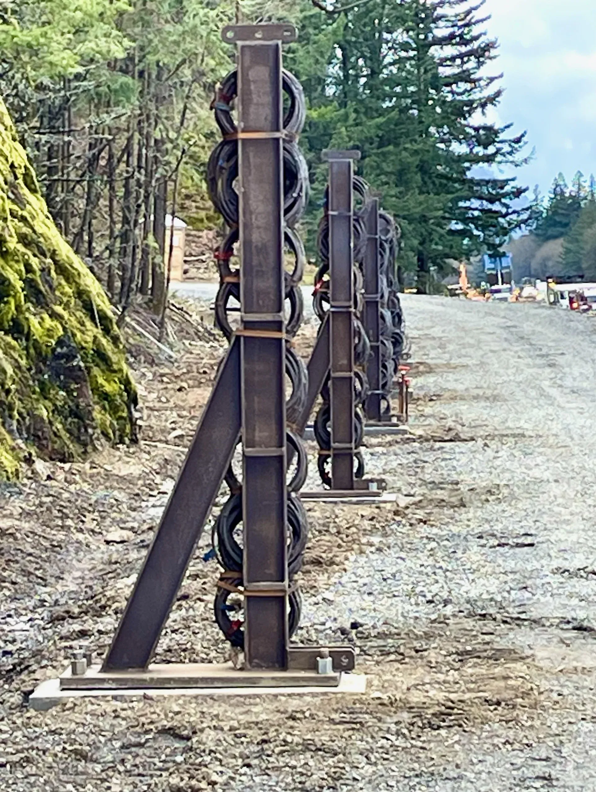
Anchor Installation
Heavy crest or face anchors drilled and grouted to design pull-out capacity, sized larger than woven-mesh anchors for the heavier system load.
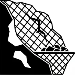
3
Panel Lift & Placement
Pre-fabricated cable-net panels lifted into position by helicopter, heavy crane, or telehandler and aligned against the rock face.
4
Seam Lacing
Adjacent panels laced with shackles or specialized cross clips at each rope intersection along the seam line.
5
Tensioning & Termination
Perimeter rope tensioned through anchor heads in drape configuration, or face bolts torqued and pull-tested in pinned configuration.