Installation follows a top-down sequence. HP-section piles are set first, either by impact or vibratory driving in soils that drive cleanly, or by drilling a shaft and setting the pile in lean-mix concrete or structural backfill where dense soil, cobbles, or shallow rock prevent driving, and where vibration must be controlled near sensitive adjacent structures. Pile alignment, plumbness, and tip elevation are verified at install. Embedment below the proposed final subgrade is sized during design to develop the passive resistance the wall will require once the excavation is opened.
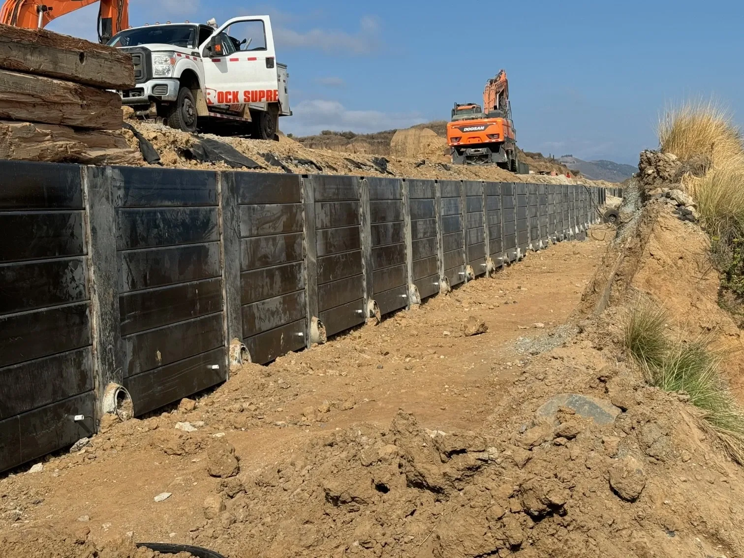
Excavation then advances in controlled lifts, typically 4 to 5 feet at a time, and lagging is placed against the exposed face between pile flanges before the next lift is taken. Voids behind the lagging are packed with pea gravel or lean concrete to engage soil arching across the flanges. At each tieback elevation, anchors are drilled at a downward inclination, grouted into competent ground behind the active failure surface, and post-tensioned against a waler beam welded or bolted across adjacent pile flanges. Excavation continues to the next anchor level, and the sequence repeats to final grade. Permanent walls receive a structural shotcrete or cast-in-place concrete facing once excavation is complete; temporary walls may leave timber lagging in place for backfill.
1
Survey and Layout
Survey pile locations and mark utilities. Verify property lines and coordinate with adjacent property owners. Establish pile spacing based on wall design and soil conditions.
2
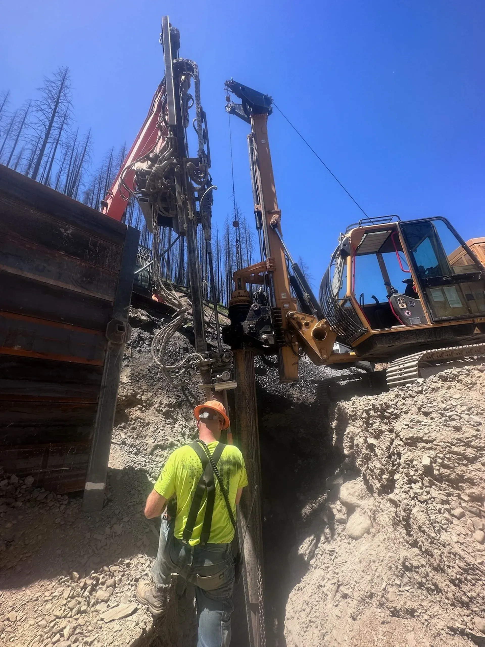
Pre-Drilling (If Required)
In dense soils, rock, or where vibration must be minimized, pre-drill pilot holes to design depth. Pre-drilling also helps navigate around utilities and obstructions.
3
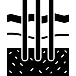
Pile Installation
Drive or vibrate H-piles to design depth and embedment. Verify pile alignment and elevation. For drilled installations, set pile in hole and grout or backfill around pile.
4
Excavation in Lifts
Excavate soil in controlled lifts (typically 4-5 feet) between pile rows. Maintain stable excavation face and install lagging promptly after each lift.
5
Lagging Installation
Install timber, precast concrete, or shotcrete lagging between pile flanges. Lagging transfers soil pressure to piles. Pack voids behind lagging with pea gravel or lean concrete.
6
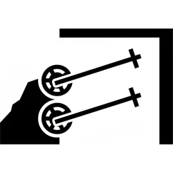
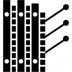
Tieback or Bracing Installation
At design elevations, install and stress tieback anchors or internal bracing to resist lateral earth pressure. Continue excavation and lagging below anchor level.
7
Wall Completion
Complete excavation to final grade. Install final lagging, drainage systems, and any architectural facing. For permanent walls, apply protective coatings or concrete facing.