Soldier Pile Walls

Soldier Pile Walls

Soldier pile walls are proven earth retention systems for stabilizing deep excavations and steep slopes. Steel beams installed at intervals with lagging placed between them provide flexible, economical support that adapts to site constraints.

100+ ft
Max Wall Height
5-10 ft
Pile Spacing
75+ yr
Service Life
500 kip
Tieback Capacity
Overview

Understanding Soldier Pile Walls

Soldier pile walls are top-down earth retention systems used for excavation shoring, deep cut support, and permanent retaining wall work. Vertical steel piles are set at regular spacing along the wall alignment, typically 5 to 10 feet on center, and lagging spans between them to retain the soil exposed as excavation advances.

The wall carries lateral earth load in bending of the soldier piles, while the lagging acts as a one-way spanning member that transfers soil pressure across each pile bay through soil arching against the flanges. Lagging can be timber, precast concrete, structural shotcrete, or steel plate, and the choice drives the wall's service life and unit cost. On highway widening and bridge approach projects, soldier pile walls and MSE walls often appear on the same job: soldier piles provide temporary shoring during substructure excavation, and once the abutment is in place, an MSE wall retains the approach embankment fill behind it. On urban basement excavations adjacent to existing buildings, the soldier piles themselves are often installed as drilled-and-grouted micropiles rather than driven HP sections, allowing the wall to advance against an immediately adjacent foundation without inducing vibration-driven settlement.

What Is a Soldier Pile Wall?

A soldier pile wall is a discrete-element earth retention system used as excavation shoring or as a permanent retaining wall. Vertical structural piles, the soldiers, are installed at regular spacing along the wall alignment, typically 5 to 10 feet on center, and lagging is placed between adjacent piles as the excavation deepens. The pile itself can be a rolled steel HP section, a wide-flange W-section, a steel pipe pile, or in older work a built-up steel section or railroad rail. The lagging can be timber, precast concrete, structural shotcrete, or steel plate. What makes the wall a soldier pile wall is the load path: each pile carries the lateral earth load in bending, while the lagging is a one-way spanning member that transfers soil pressure across each bay through soil arching against the pile flanges.

Modern U.S. practice favors HP-section steel piles for both temporary and permanent walls because of their bending and driving characteristics, and most contemporary soldier pile walls are functionally identical to H-pile walls. The broader soldier pile name remains the standard usage on excavation shoring contracts and in FHWA and state DOT specifications. Geotechnical and structural design follows FHWA GEC-4 (Ground Anchors and Anchored Systems) for tieback-supported configurations, AASHTO LRFD ยง11.8 for permanent anchored walls on transportation projects, and AISC 360 for steel pile and waler members.

Key Benefits

  • Minimal ground disturbance during installation
  • Flexible and economical system
  • Works in tight urban spaces
  • Accommodates existing utilities
  • Adaptable to varying ground conditions
The Engineering

How Soldier Pile Walls Are Built

How the system carries load in service, and how we build it on site.

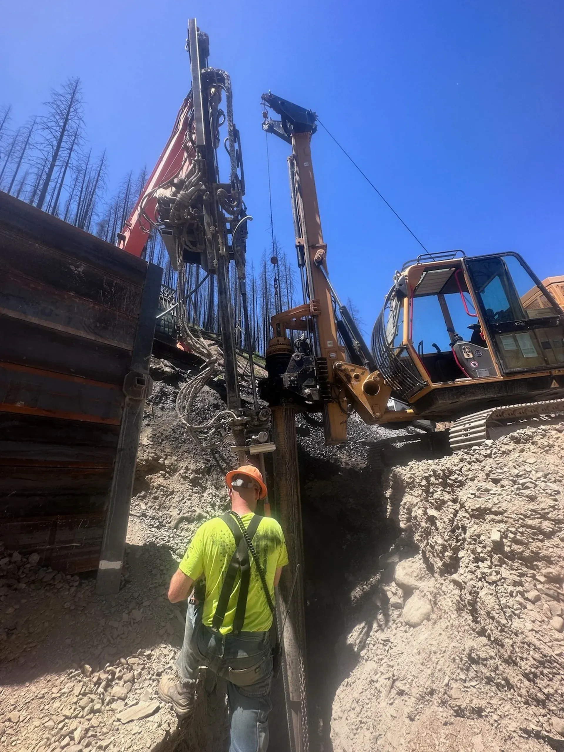
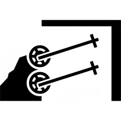
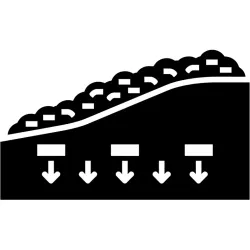
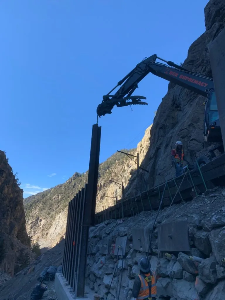
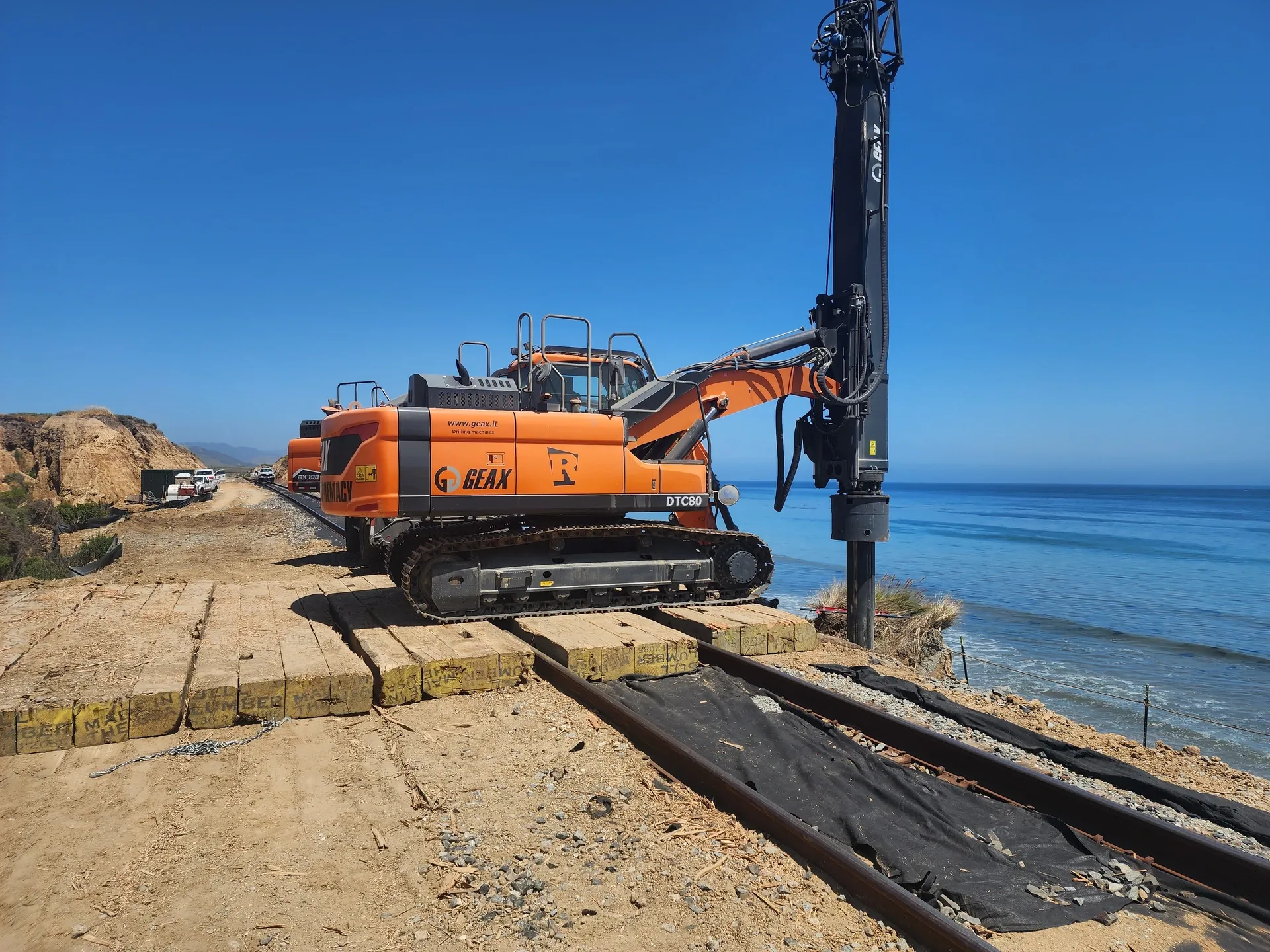
Construction follows a top-down sequence. Soldier piles are set first, either by impact or vibratory driving in soils that drive cleanly, or by drilling a vertical shaft and setting the pile in lean-mix concrete or structural backfill where dense soil, cobble fill, or shallow rock prevents driving and where vibration must be controlled near sensitive adjacent structures. Pile spacing is typically 5 to 10 feet on center, set during design based on lateral earth pressure, surcharge, lagging span capacity, and the support condition above and below the cut. Embedment below the proposed final subgrade is sized to develop the passive resistance the wall will require once the excavation is opened.

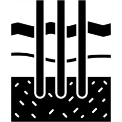
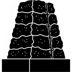
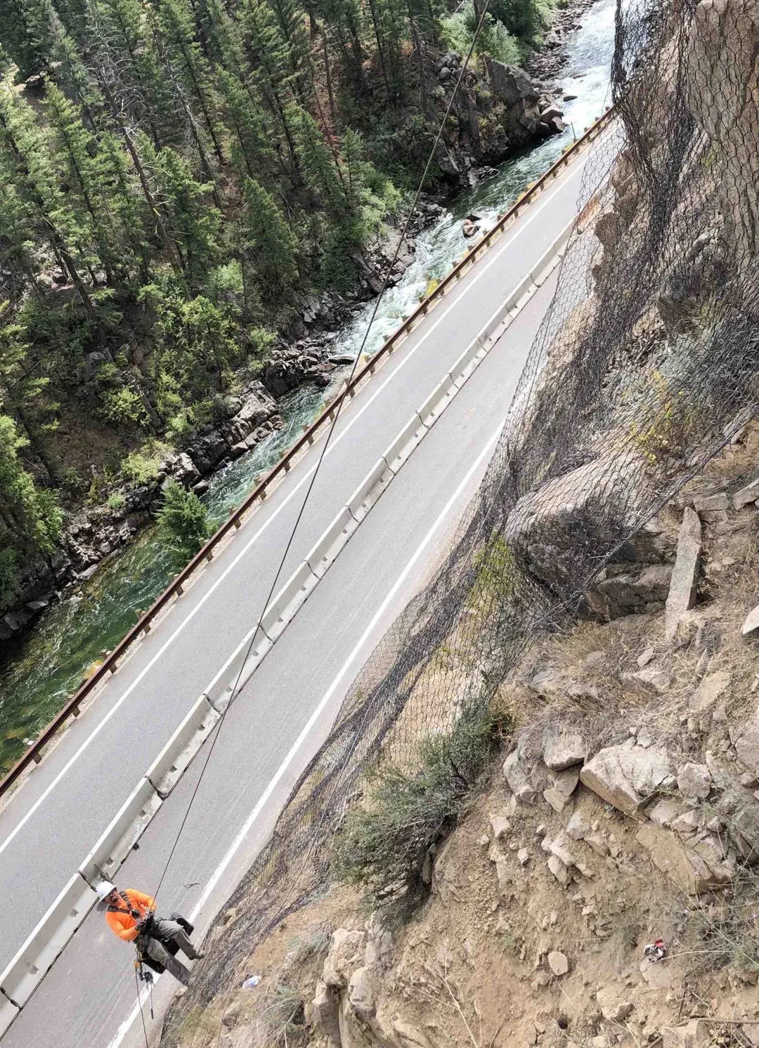
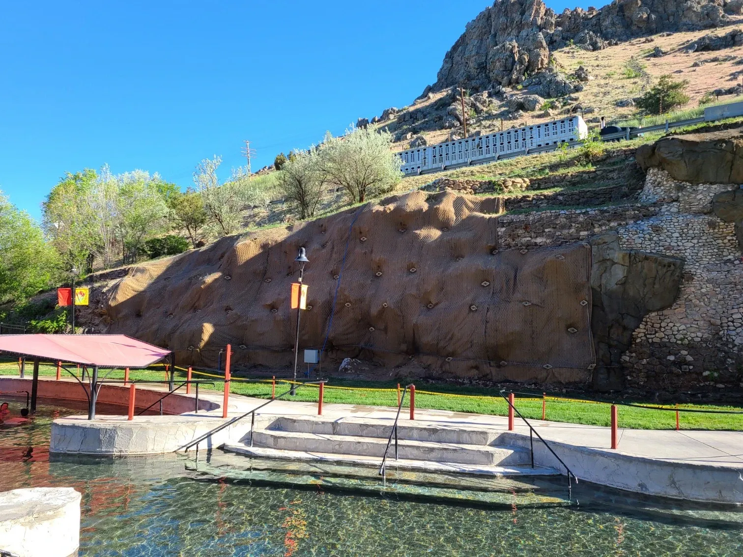
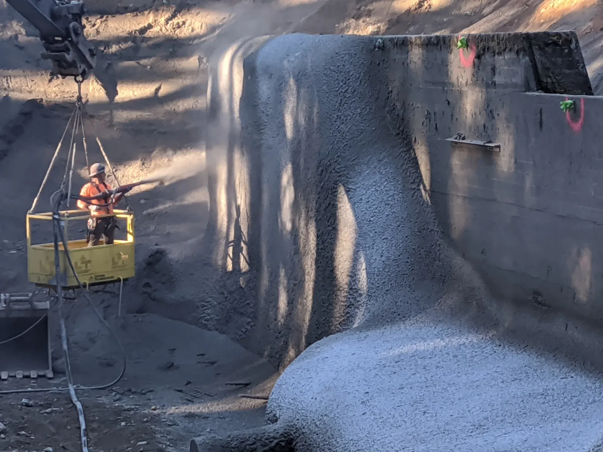
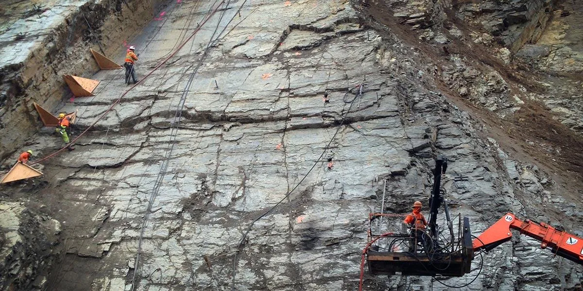
Excavation then advances in controlled lifts, typically 4 to 5 feet at a time, and lagging is installed against the exposed face between adjacent pile flanges before the next lift is taken. Voids behind the lagging are packed with pea gravel or lean concrete to engage soil arching across the flanges. For walls beyond the cantilever capacity of the embedded pile, generally about 15 to 20 feet of exposed face, tieback anchors are added at one or more elevations: drilled at a downward inclination, grouted into competent ground behind the active failure surface, and post-tensioned against a waler beam connecting adjacent piles. Excavation continues to the next anchor level, and the sequence repeats to final grade. Permanent walls receive a structural shotcrete or cast-in-place concrete facing once excavation is complete; temporary walls may leave timber lagging in place for backfill, and the steel piles are sometimes extracted at the end of the project where embedment and access permit.

1

Pile Installation

Drill and set steel soldier piles at design spacing, typically 5-10 ft on center.

2

Initial Excavation

Excavate first lift below pile tops, exposing pile flanges for lagging.

3

Lagging Installation

Place horizontal lagging between pile flanges to retain soil as excavation proceeds.

4

Tieback Installation

Install and stress anchors at each support level as required by design.

System Variants

Soldier Pile Wall Types by Lagging System

Type 01

Timber-Lagged Walls

Rough-cut timber boards, typically 3 by 12 inch or 4 by 12 inch construction-grade lumber, are placed horizontally between adjacent pile flanges as excavation advances. Timber lagging is the original lagging system and remains the most common for temporary excavation shoring because it is fast to install, accepts trim cuts to fit irregular pile spacing or utility crossings without delay, and is the lowest unit cost lagging available. Service life is the limiting factor: untreated timber decays over a few seasons of exposure, pressure-treated timber extends to perhaps 10 to 20 years depending on groundwater and soil chemistry, and the system is generally not detailed for permanent service. Many shoring projects leave the timber lagging in place after backfill is placed and accept its degradation as the soldier piles or a permanent wall behind the shoring carry the long-term load.

Type 02

Precast and Cast-in-Place Concrete Lagging

Precast concrete panels or cast-in-place concrete lagging replace timber where the wall is detailed for permanent service or where fire resistance, durability, or watertightness drive the lagging selection. Precast panels arrive at site sized for the design pile spacing and install nearly as fast as timber once spacing is verified. Cast-in-place lagging is poured against backing forms between pile flanges in lifts, slower than precast but flexible to irregular spacing and pile alignment tolerance. Concrete lagging supports design service lives of 75 years and beyond on transportation and infrastructure projects, develops higher load capacity than equivalent timber, and integrates cleanly with permanent drainage and waterproofing detailing behind the wall.

Type 03

Shotcrete-Faced Walls

Structural shotcrete is sprayed in lifts against the exposed soil face between pile flanges, reinforced with welded-wire fabric or rebar tied to the piles, to form a permanent monolithic facing. Shotcrete-faced soldier pile walls combine the discrete-pile load path with a continuous cementitious facing that conforms to the pile geometry and any irregularity in the cut. Typical facing thicknesses are 4 to 8 inches, designed to ACI 506 (Specification for Shotcrete) and detailed with weep drains to relieve hydrostatic pressure. The system suits permanent below-grade walls, tunnel-portal approaches, and architectural exposed walls where the finish surface is sculpted or textured, and it makes the most efficient use of irregular pile spacing on walls that bend in plan or follow a curving alignment.

Side By Side

Soldier Pile Walls vs Other Excavation Support Systems

VS

Soldier Pile Wall vs Soil Nail Wall

The two systems compete head-to-head on shoring and earth retention bids, and the selection resolves along the load-mechanism axis. Soil nail walls reinforce the entire soil mass in tension with closely spaced grouted bars, turning the soil itself into a structural element, while soldier pile walls concentrate lateral load at discrete vertical piles with lagging spanning between. Soil nail walls typically install for 25 to 50 percent less than equivalent-height soldier pile walls and become permanent structures by design, with shotcrete facing applied as construction proceeds. Soldier pile walls are preferred where the excavation behind the wall must remain open for utility access, deeper anchor installation, or cut-and-cover construction, since soil nailing forecloses any future intrusion into the reinforced zone behind the face. Soldier pile walls are also the standard choice when the steel piles are intended for extraction at the end of a temporary shoring contract.

VS

Soldier Pile Wall vs Sheet Pile Wall

Both are top-down driven steel systems, but the structural geometry differs sharply. Sheet piles interlock continuously along the wall alignment, providing both lateral bending capacity and a near-watertight cutoff that controls groundwater inflow into the excavation, and they are the standard choice for waterfront bulkheads, cofferdams, and dewatering cutoffs. Soldier pile walls space discrete steel piles at intervals with lagging spanning between, giving the system better drainage behind the lagging, easier accommodation of utility crossings, and meaningfully better economics on dry sites at greater wall heights. Where the exposed face exceeds about 30 feet, where multi-tier tieback anchor systems are required, or where a permanent shotcrete or cast-in-place facing will eventually replace the lagging, soldier pile walls are the more efficient system.

VS

Soldier Pile Wall vs Secant Pile Wall

A secant pile wall is a continuous wall of overlapping drilled concrete piles, alternating reinforced primary piles and unreinforced secondary piles, providing both structural capacity and a near-watertight cutoff. Installed cost per square foot of face runs roughly 1.5 to 3 times that of an equivalent-height soldier pile wall. Secant piles are the right tool when groundwater control is critical, when settlement of adjacent structures must be tightly limited, or when a permanent below-grade water-resistant wall is required as part of the finished building. Soldier pile walls remain the more economical choice on dry sites where lagging and drainage behind the wall are acceptable, and where the lagging will eventually be hidden behind backfill or replaced by shotcrete.

Not sure which system fits? We'll walk through the tradeoffs for your site conditions.

Talk Through Your Options
Where It Fits

Common Applications and Project Types

Soldier pile walls dominate excavation shoring on commercial and infrastructure projects where speed of installation, depth capacity, and tolerance of utility conflicts are decisive. Typical projects include downtown office and residential basement and below-grade parking cuts of 30 to over 100 feet, transit station and tunnel-portal excavations, bridge abutment and wing-wall foundation excavations, highway widening and grade-separation work, and slope stabilization where a discrete-pile retention system is preferable to a continuous wall. The system is also widely used as temporary shoring during construction of permanent MSE walls, cast-in-place retaining walls, or below-grade structures, since the soldier piles can often be extracted at the end of the contract where access permits. State DOT and AASHTO-governed projects use permanent soldier pile walls with shotcrete or cast-in-place concrete facing for service lives of 75 years and beyond, especially where a tieback-anchored system is more economical than the equivalent secant pile wall or sheet pile alternative. Slope stabilization use cases include cut-slope retention, head-scarp stabilization on shallow landslide repairs, and roadway widening on side-hill alignments where the upslope cut requires permanent retention.

Building basement excavations
Highway widening projects
Bridge approaches and abutments
Temporary and permanent shoring
Slope stabilization
Utility protection during excavation
Benefits

Key Advantages

Design Flexibility

Cantilever, single-braced, or multi-tiered anchor systems adapt to any excavation depth and site constraint.

Utility Accommodation

Pile spacing adjusts around existing utilities; lagging can be modified to provide access for utility work.

Rapid Construction

Top-down construction proceeds quickly, lagging installed as excavation advances without waiting for concrete cure.

Cost Effective

Less material than continuous walls; timber lagging provides economical temporary support.

Permanent or Temporary

Systems can be designed for construction-phase support or permanent earth retention with appropriate materials.

Engineering

Technical Considerations

Soil/Rock Conditions

Works in most soil conditions. Pile embedment into competent material provides passive resistance. May need casing in caving soils during drilling.

Groundwater

Lagging allows some drainage; continuous shotcrete facing with weep drains used in high groundwater conditions.

Load Capacity

Pile section size and spacing determined by lateral earth pressure, surcharge loads, and support spacing.

Spacing

Typical pile spacing 5-10 ft. Closer spacing for higher loads or deeper excavations. Tieback spacing matches pile locations.

Installation Method

Piles installed by drilling and setting or driving. Excavation proceeds in lifts with lagging installed as soil is exposed.

Equipment Used

  • Drill rigs or pile drivers
  • Excavation equipment
  • Tieback drilling rigs
  • Lagging handling equipment
  • Stressing jacks for tiebacks

Limitations

  • Not watertight without additional treatment
  • Limited passive resistance in soft soils
  • Tieback easements may be required
  • Timber lagging has limited service life

Technical Specifications

Pile Type
W-Section / HP Section
Spacing
5 ft to 10 ft on center
Lagging
Timber / Precast / Shotcrete
Support
Cantilever / Braced / Anchored
Codes And References

Engineering Standards and References

FHWA

GEC-4 (FHWA-IF-99-015)

Ground Anchors and Anchored Systems

The canonical practitioner manual for tieback-anchored walls including soldier pile systems. Covers geotechnical design, structural analysis, corrosion protection, anchor testing, and construction inspection. Cited by virtually every state DOT specification for permanent anchored excavation support.

AASHTO

LRFD ยง11.8

Bridge Design Specifications, Anchored Walls

Provides load and resistance factors, design service-life requirements, and load combinations for permanent soldier pile and other anchored walls on transportation projects. Governs the geotechnical and structural reliability framework used on state DOT and federal-aid jobs.

AISC

360

Specification for Structural Steel Buildings

Governs the structural design of soldier piles and waler beams for both temporary and permanent walls, including bending, shear, axial, and combined-loading provisions used in member sizing of HP and W-section piles.

OSHA

29 CFR 1926 Subpart P

Excavations Standard

Sets the federal safety framework for excavation shoring, including soil classification, protective system selection, and the requirement that engineered shoring designs over 20 feet bear a registered professional engineer's seal. Applies to all soldier pile walls used as construction-phase excavation support.

Expertise

Why Choose Rock Supremacy for Soldier Pile Walls

Integrated Installation

We install piles, tiebacks, and facing with our own crews for seamless coordination and quality control.

Urban Experience

Extensive experience in constrained urban sites with utility conflicts and adjacent structure protection.

Flexible Equipment

Multiple drill rigs from compact to heavy-duty allow efficient installation in any site condition.

Design Assistance

We work with engineers to optimize designs for constructability and cost-effectiveness.

Complete Solutions

Soldier pile walls combined with drainage, waterproofing, and facing for permanent applications.

Questions

Soldier Pile Walls FAQ

A soldier pile is a vertical structural steel member, set at regular spacing along a wall alignment, that carries the lateral earth load in bending while lagging spans between adjacent piles to retain the soil. The name comes from the regular drill-team-line spacing of the piles. The pile itself can be a rolled steel HP section, a wide-flange W-section, a steel pipe pile, or in older work a built-up steel section or railroad rail. Modern U.S. permanent and high-capacity walls almost always use HP-section steel piles, which are engineered specifically for use as driven or drilled foundation and earth-retention members.
The terms are largely interchangeable in current U.S. practice. Soldier pile is the broader name for any vertical structural pile spaced along a wall alignment with lagging between, regardless of section type. H-pile specifically denotes a rolled steel HP-section pile, the AISC-designated wide-flange shape with parallel flanges of equal thickness engineered for use as a foundation pile. Most modern soldier pile walls use HP sections because of their bending and driving characteristics, and engineers often write soldier pile and <a href="/techniques/h-pile-walls">H-pile</a> interchangeably in shop drawings and specifications. The distinction matters only when the section is something other than an HP, for example a wide-flange W-section, a steel pipe, or a built-up section.
Cantilevered soldier pile walls (with no anchors) typically support 15 to 20 feet of exposed face, with the limit set by pile bending capacity and the available embedment depth for passive resistance. Tieback-anchored walls extend that range substantially. Single-tier anchored walls reach 25 to 35 feet, and multi-tier anchored systems support permanent walls more than 100 feet tall on transit, bridge, and below-grade-parking projects. The deepest soldier pile and tieback systems in U.S. practice have been used for permanent service-life walls on subway and light-rail station cuts.
Soldier pile walls space discrete steel piles at intervals (typically 5 to 10 feet on center) with lagging spanning between, while sheet pile walls use continuous interlocking steel sections (Z, U, or flat profiles) driven side-by-side along the wall alignment. Sheet piles provide a near-watertight cutoff and are the standard choice for waterfront bulkheads, cofferdams, and dewatering applications. Soldier pile walls have no inherent water cutoff but are more economical at greater wall heights, accommodate utility crossings more easily, and pair efficiently with tieback anchors for deep multi-tier excavation support.
<a href="/techniques/soil-nailing">Soil nail walls</a> reinforce the entire soil mass in tension with closely spaced grouted bars, turning the soil itself into a structural element, while soldier pile walls concentrate lateral load at discrete vertical piles with lagging spanning between. Soil nailing typically installs for 25 to 50 percent less than equivalent-height soldier pile walls and becomes a permanent structure by design, with shotcrete facing applied as construction proceeds. Soldier pile walls are preferred where the excavation behind the wall must remain open for utility access, deeper anchor installation, or cut-and-cover construction, since soil nailing forecloses any future intrusion into the reinforced zone. Soldier pile walls are also the standard choice when the steel piles are intended for extraction at the end of a temporary shoring contract.
Soldier piles are installed by one of two methods. Driven installations use an impact or vibratory hammer to drive the pile to design embedment, which is fastest and lowest cost in soils that drive cleanly such as medium-dense sands, silts, and soft to medium clays, but produces vibration and noise that limits use within roughly 50 to 100 feet of sensitive structures. Drilled-and-set installations advance a vertical shaft to design depth, set the pile in the open hole, and backfill the annular space with structural concrete or sand-cement grout. Drilled installations work in any ground condition including dense soils, cobble fills, and weathered rock, eliminate driving vibration, and allow precise placement around buried utilities, at meaningfully higher cost per pile.
Pricing is project-specific and depends on wall height, pile spacing and section size, the number of tieback levels, lagging type, soil and groundwater conditions, and access. As a generic capability band for budgeting, soldier pile walls typically install for less than equivalent <a href="/techniques/secant-pile-walls">secant pile walls</a> or sheet-pile-with-cap walls of comparable height, and 25 to 50 percent more than equivalent-height <a href="/techniques/soil-nailing">soil nail walls</a>. Cantilevered systems on smaller commercial cuts sit at the low end of the band; multi-tier permanent anchored walls on transit and bridge projects sit at the high end. Final pricing requires geotechnical data and project drawings; we can provide a project-specific estimate from preliminary information.
Yes. Permanent soldier pile walls use concrete or structural shotcrete lagging with corrosion protection on the steel pile and are designed and detailed for service lives of 75 years and beyond on AASHTO-governed projects. Wall geometry, lagging selection, drainage detailing, and corrosion protection all reflect the intended service life. Where a tieback-anchored permanent system is more economical than the equivalent secant pile or sheet pile alternative, soldier pile walls are commonly the preferred permanent choice on state DOT and federal-aid jobs.
Utility locates are confirmed before design, and pile positions are adjusted in plan to clear active utilities by the required offset. Where a pile must be set close to a utility crossing, drilled-and-set installation replaces driving to eliminate vibration and to allow careful spotting of the shaft. Lagging detailing is modified locally to span around utility crossings, and where a utility cannot be relocated, support framing or temporary protective casing is added. The discrete-pile geometry of the system is what makes that coordination practical compared with continuous-wall alternatives.
Selection depends on wall service life, groundwater conditions, fire resistance requirements, and budget. Timber lagging is the lowest-cost and fastest-installed option and remains the standard for temporary excavation shoring; service life is generally limited to 10 to 20 years even with pressure treatment. Precast or cast-in-place concrete lagging supports permanent service lives of 75 years and beyond and integrates cleanly with permanent drainage and waterproofing detailing. Structural shotcrete sprayed against the soil face between pile flanges produces a continuous monolithic facing well suited to permanent below-grade walls and to architectural exposed walls, with ACI 506 governing the design and quality control.
Testimonials

Client Testimonials

Trusted by DOTs, engineering firms, and property owners nationwide.

Contact

Deploy Us

Ready to discuss your project? Our team is standing by to assess your site conditions and develop a custom solution using Soldier Pile Walls and other proven techniques.

Emergency (24/7)

(541) 383-7625

Bidding & Estimates

Info@RockSupremacy.com

Headquarters

Western Division (HQ)
65147 N Hwy 97
Bend, OR 97701
Eastern Division
915 Millennium Ct
Blountville, TN 37617

Licensed in CO, UT, WY, ID, MT, CA, WA, OR, TN, VA

Request Consultation

Methods

Related Techniques

Explore other engineering methods we use to deliver comprehensive geotechnical solutions.