Micropiles

Micropiles

Micropiles are small-diameter, high-strength deep foundation elements used to transfer loads into competent ground. Their versatility makes them ideal for underpinning, slope stabilization, and situations with limited access or difficult geology.

300+
Ton Capacity
100+
Ft Depth
6 ft
Min Headroom
Any
Ground Type
Overview

Understanding Micropiles

Micropiles are small-diameter, drilled, grouted, and reinforced deep foundation elements that develop high axial capacity through the bond between the grout column and competent ground. Originally developed in Italy in the 1950s by Fernando Lizzi as the palo radice, or root pile, the technique was first used to underpin historic buildings without driving vibration, then adapted for seismic retrofit and modern deep-foundation work as it entered US practice in the 1970s. Engineers now specify micropiles wherever confined access, vibration-sensitive adjacent structures, complex stratigraphy with cobbles or weathered rock, or extreme single-element capacity requirements rule out driven piles or conventional drilled shafts. A typical micropile is 5 to 12 inches in diameter, reaches 30 to 100 feet of bond depth, and develops 50 to 300 tons of capacity, all installable from a low-headroom rig with as little as 6 to 8 feet of clearance.

What Is a Micropile?

The micropile was developed in Italy in the 1950s by Fernando Lizzi as the palo radice, or root pile, originally for underpinning historic buildings where conventional driven piles would have transmitted damaging vibration into the structure. The technique entered US practice in the 1970s for seismic retrofit of bridges and buildings and was codified federally through FHWA reference manuals and AASHTO LRFD provisions over the 1990s and 2000s. A micropile is a small-diameter, drilled, grouted, and reinforced deep foundation element that develops axial capacity through the bond between the grout column and the surrounding ground.

Three components work together. The reinforcement is either a permanent steel casing, a high-strength threaded bar, or both, depending on whether the pile must resist lateral and bending loads in addition to axial load. The grout body is neat cement, placed by tremie line and typically pressurized to densify the bond zone against the surrounding ground. The structural connection at the pile head is a pile cap, bracket, or grade beam that transfers structural load into the reinforcement. Diameters typically run from 5 to 12 inches, with single-pile capacities in the 50 to 300 ton range depending on bond length, ground stiffness, and grouting method.

Key Benefits

  • High structural capacity in small diameter
  • Works in virtually any soil or rock condition
  • Minimal vibration and disturbance
  • Ideal for remote or constrained sites
  • Excellent corrosion resistance with protective coatings
The Engineering

How Micropile Installation Works

How the system carries load in service, and how we build it on site.

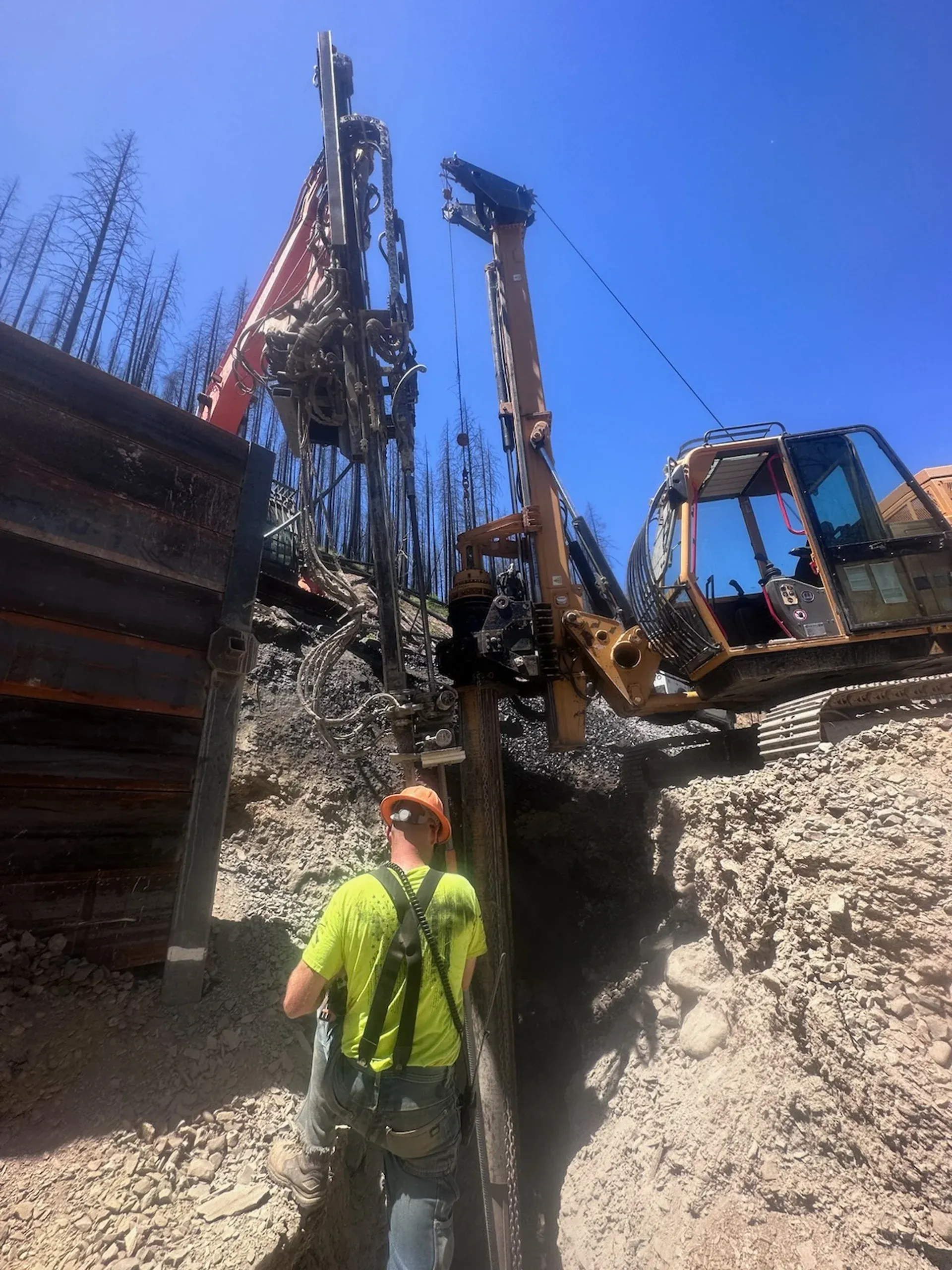
Construction is a single drilled-and-grouted pass per pile. A borehole is advanced through overburden into competent bearing material using rotary or rotary-percussive drilling, with temporary casing or hollow-bar drilling carrying the hole open through caving ground. Permanent steel casing, a threaded reinforcing bar with centralizers, or a hollow self-drilling bar is set in the hole. Cement grout is placed by tremie line from the toe upward, then pressurized through the casing or a sleeved port pipe to densify the bond zone. Crews construct the pile cap, bearing plate, or bracket that transfers structural load into the reinforcing.

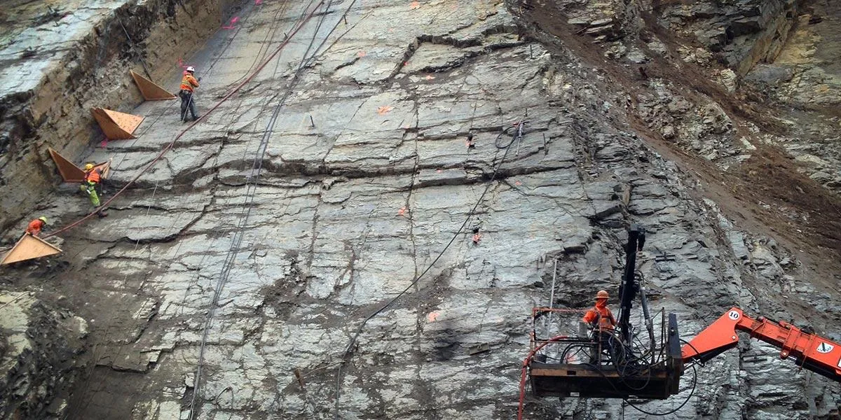
Grouting method governs capacity, and the FHWA reference manual classifies four standard variants. Type A piles are gravity-grouted, used predominantly in competent rock where the bore stays open. Type B piles are pressure-grouted through the casing during withdrawal, typically at 30 to 150 psi, with pressurization fracturing and densifying the surrounding soil along the bond zone. Type C and Type D piles are post-grouted through a sleeved port pipe at higher pressures, 300 psi and above, in one or multiple secondary passes, used where extreme capacity is required from limited bond length. Across every type, load transfer follows the same path: load enters the reinforcing at the pile head, travels axially along its length, and transfers from grout into ground through skin friction in the bond zone. Capacity is sensitive to grouting pressure, bond length, and ground stiffness, which is why every project requires load testing per AASHTO and FHWA protocols.

1

Borehole Drilling

Drill a borehole into competent bearing strata using rotary or percussion methods.

2

Reinforcement Installation

Install high-strength steel reinforcing bar or casing with centralizers.

3

Pressure Grouting

Grout the pile to form a high-capacity load-transfer element bonded to surrounding ground.

4

Connection

Connect piles to the structure or stabilization system using caps, brackets, or grade beams.

System Variants

Types of Micropiles

Type 01

Cased Micropiles

Cased micropiles use a permanent steel casing along the upper, non-bonded portion of the pile, with a threaded bar and grout filling the bond zone in competent material below. The casing carries the structural load through overburden, resists lateral and bending forces, and protects against corrosion in aggressive ground or fill. Used where the pile must develop combined axial and lateral capacity, where overburden contains aggressive water or chlorides, or where the upper soil cannot be relied on for friction. Standard for bridge retrofits, seismic upgrades, and any application with significant lateral demand.

Type 02

Bond-Bar (Uncased) Micropiles

Bond-bar micropiles are reinforced with a threaded bar grouted directly into a stable rock socket, with no permanent casing in the bond zone. The bar develops capacity through grout-to-rock skin friction over the bonded length, typically 10 to 30 feet seated in competent rock. This is the standard configuration for axial-load-only applications in rock, including transmission tower anchors, wind turbine foundations, and structural underpinning where the bedrock is at a workable depth. Cost per linear foot is meaningfully lower than fully cased systems.

Type 03

Hollow-Bar Self-Drilling Micropiles

Hollow-bar micropiles use a self-drilling threaded bar that doubles as the drill rod, with a sacrificial drill bit at the toe. Grout is pumped through the hollow bar during drilling, both flushing cuttings out of the hole and forming the grout column in a single pass. Eliminating the casing-and-tremie sequence makes hollow-bar systems the default in collapsing soils, urban underpinning where casing handling is impractical, and emergency stabilization where speed governs. Higher per-foot material cost is offset by faster production and a smaller equipment footprint.

Side By Side

Micropiles vs Other Deep Foundation Systems

VS

Micropile vs Driven Pile

The defining distinction is install method, which drives every other tradeoff. Driven piles are forced into the ground by impact or vibratory hammers, displacing soil radially and developing capacity through end bearing and skin friction on the displaced surface. Micropiles are drilled and grouted, with no soil displacement, and develop capacity through grout-to-ground bond. Driven piles are typically lower cost per ton of capacity in open sites with simple stratigraphy and no vibration constraints. Micropiles are preferred where confined access, sensitive adjacent structures, vibration-prone soils, or complex stratigraphy with cobbles, boulders, or weathered rock would prevent driving. Driven piles often cannot work in karst terrain or interbedded soils, where micropiles handle variable conditions routinely.

VS

Micropile vs Drilled Shaft

Both systems are drilled, but the geometry and capacity model differ sharply. Drilled shafts, also called caissons, are large-diameter elements, typically 24 to 120 inches, reinforced with a rebar cage and tremied with concrete, developing very high single-element capacity primarily through end bearing on rock or dense soil. Micropiles are small-diameter elements, typically 5 to 12 inches, reinforced with high-strength steel and pressurized grout, developing high unit capacity from a much smaller cross-section. A drilled shaft requires open-air drilling with large equipment and substantial site footprint. Micropile groups deliver comparable total capacity from low-headroom rigs in basements, on bridge decks, and in any tight-access setting where a drilled shaft cannot be installed.

VS

Micropile vs Helical Pier

Both are small-diameter deep foundation elements, but the engineering envelope differs by an order of magnitude. Helical piers are screw-in steel shafts with helical bearing plates, installed with a hydraulic torque head, with single-pier capacities typically in the 20 to 50 kip range and most installations in the 5 to 30 foot depth band. They are the standard for residential underpinning, light commercial additions, and tower foundations on soft to medium soils. Micropiles develop capacities from 50 to 300 tons and reach 100+ feet through the entire stratigraphy, including bedrock. Helical piers install faster and cleaner with no spoil. Micropiles cost more per pile but cover the heavy commercial, infrastructure, seismic retrofit, and rock-bonded foundation envelope that helicals cannot serve.

Not sure which system fits? We'll walk through the tradeoffs for your site conditions.

Talk Through Your Options
Where It Fits

Common Applications and Project Types

Federal and state DOT work drives a meaningful share of US micropile installation volume, with bridge pier reinforcement, abutment underpinning, and seismic retrofit as the most frequent assignments. Beyond transportation, micropiles are heavily specified for foundation underpinning of existing buildings where conventional driven or large-diameter drilled-shaft equipment cannot access the site, including basements with restricted headroom and structures sensitive to vibration. Slope stabilization in landslide-affected zones uses high-capacity micropiles to transfer building loads through the failure surface to stable bearing strata, often combined with tieback anchors resisting lateral demand. Other recurring applications include transmission tower and wind turbine foundations, industrial equipment supports, dam and spillway stabilization, and historic structure preservation where adjacent driven piles would cause settlement or vibration damage.

Foundation repair and underpinning
Slope stabilization
Retaining wall enhancement
Bridge abutment reinforcement
Support in restricted-access urban or mountainous sites
Upgrading existing foundations for increased loads
Benefits

Key Advantages

High Capacity, Small Footprint

Micropiles deliver 50-300+ ton capacity from piles as small as 5 inches diameter.

Low Headroom Capability

Specialized equipment operates in spaces as low as 6-8 feet, ideal for basements and under bridges.

Minimal Disturbance

Low-vibration drilling protects adjacent structures and allows work in sensitive environments.

Universal Ground Conditions

Micropiles work in any soil or rock, from soft clay to hard granite, adapting to variable conditions.

Immediate Load Capacity

Grout reaches design strength within days, allowing rapid load transfer to the pile system.

Engineering

Technical Considerations

Soil/Rock Conditions

Micropiles work in all ground conditions. Cased piles for caving soils; uncased for stable rock. Bond length in competent material determines capacity.

Groundwater

Drilling and grouting methods adapted for wet conditions. Hollow-bar systems allow simultaneous drilling and grouting in difficult ground.

Load Capacity

Capacity depends on pile diameter, reinforcement, grout strength, and bond length. All piles load-tested to verify design capacity.

Spacing

Pile spacing determined by load requirements and group effects. Minimum spacing typically 3 pile diameters center-to-center.

Installation Method

Rotary or percussion drilling through overburden into rock. Reinforcement placed with centralizers, grouted under pressure from bottom-up.

Equipment Used

  • Low-headroom drill rigs
  • Rotary and percussion drill tooling
  • Grout mixing and pumping equipment
  • High-strength reinforcing steel
  • Load testing equipment

Limitations

  • Higher cost per unit load than driven piles
  • Requires competent material for bond zone
  • Drilling spoils require management
  • Group effects may reduce capacity

Technical Specifications

Diameter
5" to 12"
Depth
20 ft to 100+ ft
Types
Cased / Uncased
Capacity
50 to 300+ Tons
Codes And References

Engineering Standards and References

FHWA

NHI-05-039

Micropile Design and Construction Reference Manual

The canonical practitioner document covering Type A/B/C/D grouting classification, structural and geotechnical design, corrosion protection, and load testing requirements. Cited by virtually every state DOT and federal specification.

AASHTO

LRFD §10.9

Bridge Design Specifications

Provides LRFD load and resistance factors, corrosion protection requirements, and load test verification protocols for micropiles on transportation projects.

IBC

§1810

International Building Code, Deep Foundations

Building code provisions covering deep foundation design for non-transportation projects, including micropile structural requirements, corrosion protection, and load test acceptance criteria.

Expertise

Why Choose Rock Supremacy for Micropiles

Specialized Access Equipment

Low-headroom rigs and steep-terrain platforms allow installation where standard equipment cannot operate.

Type A Through D Grouting

Practice covers gravity-grouted (Type A), pressure-grouted (Type B), and post-grouted (Type C/D) micropiles per FHWA classification, supporting design capacities through marginal soils as well as competent rock.

Advanced Grouting

Pressure grouting techniques maximize pile capacity and ensure complete bond zone development.

Complete Load Testing

All piles tested to verify design capacity with full documentation for owner records.

Integrated Solutions

Micropiles combined with tiebacks, drainage, and other techniques for comprehensive stabilization.

Questions

Micropiles FAQ

A micropile is a small-diameter, drilled, grouted, and reinforced deep foundation element, typically 5 to 12 inches in diameter, that develops axial capacity through bond between the grout column and competent ground. Reinforcement is either a permanent steel casing, a high-strength threaded bar, or a hollow self-drilling bar. Capacity is generated by grout-to-ground skin friction along the bonded length in rock or dense soil. Originally developed in Italy in the 1950s by Fernando Lizzi for underpinning historic structures, micropiles are now codified in FHWA NHI-05-039 and AASHTO LRFD §10.9 and used for foundation underpinning, seismic retrofit, slope stabilization, and confined-access deep foundations.
Single micropiles typically develop 50 to 300 tons of capacity depending on diameter, reinforcement, bond length, and ground stiffness, with FHWA reporting service loads from 200 to 600 kips and higher in competent rock. Multiple piles connected by a pile cap or grade beam can support very heavy structures, including bridge piers, transmission towers, and industrial equipment foundations. Capacity is verified on every project by load testing per AASHTO and FHWA protocols, with a sacrificial verification test plus proof tests on selected production piles.
Driven piles are forced into the ground by impact or vibratory hammers, displacing soil radially and developing capacity through end bearing and skin friction on the displaced surface. Micropiles are drilled and grouted, with no soil displacement, and develop capacity through grout-to-ground bond. Driven piles are typically lower cost per ton in open sites with simple stratigraphy. Micropiles are preferred where confined access, sensitive adjacent structures, vibration-prone soils, or complex stratigraphy with cobbles, boulders, or weathered rock would prevent driving.
Both are drilled deep foundations, but the geometry and capacity model differ. Drilled shafts, also called caissons, are large-diameter elements (24 to 120 inches), reinforced with a rebar cage and tremied with concrete, developing very high single-element capacity primarily through end bearing. Micropiles are small-diameter (5 to 12 inches), reinforced with high-strength steel and pressurized grout, developing high unit capacity from a much smaller cross-section. A drilled shaft requires open-air drilling with large equipment. Micropile groups deliver comparable total capacity from low-headroom rigs in basements, on bridge decks, and in any tight-access setting where a drilled shaft cannot be installed.
Helical piers are screw-in steel shafts with helical bearing plates, installed with a hydraulic torque head, that develop capacity primarily through end bearing on the helices in soft to medium soils. Single-pier capacities typically run 20 to 50 kips and most installations are 5 to 30 feet deep. Micropiles are drilled, grouted, and bonded into competent rock or dense soil, with single-pile capacities of 50 to 300 tons reaching 100+ feet of depth. Helical piers are the standard for residential underpinning and light commercial additions on soft soils. Micropiles cover the heavy commercial, infrastructure, and rock-bonded foundation envelope that helicals cannot serve.
Yes. Specialized low-headroom drill rigs operate in spaces with as little as 6 to 8 feet of clearance, allowing micropile installation inside basements, under bridge decks, and in any confined-access environment where conventional drill rigs cannot enter. Drilled, grouted installation produces minimal vibration, which is why micropiles are the standard choice for underpinning of historic structures and buildings sensitive to construction-induced settlement.
Micropiles are routinely installed to 100+ feet, with depth governed by the location of competent bearing material rather than equipment limitations. In areas with deep soft alluvium or organics, piles extend through the full overburden until reaching rock or dense, competent soil. Bond zone length, typically 10 to 30 feet, is set during design as a function of required capacity, ground stiffness, and grouting method per FHWA NHI-05-039 procedures.
Production rates depend on depth, ground conditions, access, and grouting method. Experienced crews typically install 2 to 6 piles per shift on routine work. Grout reaches design strength within 7 to 14 days, and load testing schedules incorporate this cure window. Hollow-bar self-drilling systems are typically the fastest installation method in caving ground; cased systems with post-grouting take longer per pile but develop higher capacity from limited bond length.
In the United States, micropile design follows three primary references. FHWA Publication NHI-05-039, the Micropile Design and Construction Reference Manual, is the canonical practitioner document covering Type A/B/C/D grouting classification, geotechnical and structural design, corrosion protection, and load testing. AASHTO LRFD Bridge Design Specifications, Section 10.9, provides load and resistance factors and load test verification protocols for transportation projects. The International Building Code, Section 1810, governs micropile use on building projects and sets corrosion-protection and acceptance-criteria requirements. State DOT specifications typically reference these documents and add jurisdiction-specific provisions for testing and quality control.
Testimonials

Client Testimonials

Trusted by DOTs, engineering firms, and property owners nationwide.

Contact

Deploy Us

Ready to discuss your project? Our team is standing by to assess your site conditions and develop a custom solution using Micropiles and other proven techniques.

Emergency (24/7)

(541) 383-7625

Bidding & Estimates

Info@RockSupremacy.com

Headquarters

Western Division (HQ)
65147 N Hwy 97
Bend, OR 97701
Eastern Division
915 Millennium Ct
Blountville, TN 37617

Licensed in CO, UT, WY, ID, MT, CA, WA, OR, TN, VA

Request Consultation