Rockfall Barriers & Fences

Rockfall Barriers & Fences

Engineered catch systems that intercept falling rock before it reaches roadways, railways, or infrastructure. Flexible posts, energy-absorbing brake elements, and ring or cable nets dissipate impact energy through controlled deformation.

100-5,000+ kJ
Energy Class Range
25 ft
Max Barrier Height
EAD 340059
Certification Standard
Reusable
After Impact
Overview

Understanding Rockfall Barriers

Rockfall barriers are flexible catch systems that intercept falling rock at the base of a slope and absorb impact energy through deformation rather than rigid resistance. A typical kit pairs hinged steel posts on rock-anchored or concrete foundations with upslope and lateral support cables, energy-dissipating brake elements, and a ring net or cable net spanning the post array. When rock strikes the net, the net deforms inward and pulls on the support cables, the brake elements extend through controlled friction or ring deformation, and the residual load transfers cleanly into the foundations.

Standard rockfall barriers cover the 100 to 3,000 kJ range that handles the dominant volume of US highway, rail corridor, and mining haul road catch-fence work. For higher-energy sites with large blocks or long fall heights, the same kit family extends to high-energy ring-net barriers rated up to 10,000 kJ. Where slope geometry allows mid-slope interception, a mid-slope attenuator reduces impact energy before it reaches the toe barrier. Barriers pair with draped mesh on the upper slope and rock scaling at the source for a complete mesh and barrier system.

What Is a Rockfall Barrier?

A rockfall barrier is an engineered, prefabricated catch system installed across the line of falling rock to stop and retain blocks before they strike a roadway, railway, or structure. Modern flexible barriers were developed in the Swiss and Italian alpine corridors during the 1980s and 1990s, replacing earlier rigid catch fences with kits engineered to deform predictably and dissipate impact energy through brake elements. The technology was codified by the European Organisation for Technical Approvals as ETAG 027 in 2008, then converted under the Construction Products Regulation to EAD 340059-00-0106, which remains the controlling certification framework for falling rock protection kits sold worldwide.

A barrier is a kit, not a single component. The system comprises foundations (rock anchors, micropiles, or concrete footings), hinged steel posts on shear-pin or articulated base plates, upslope and lateral support cables, brake elements (friction-plate, ring-deformation, or pipe-deformation devices that extend in tension under load), and an interception net (interlocking steel rings, woven wire rope, or chain-link). Energy class is verified by full-scale vertical-drop impact test against two thresholds: the Service Energy Level (SEL), which is one-third of the rated capacity applied as two consecutive hits with no functional damage, and the Maximum Energy Level (MEL), which is the rated capacity applied as a single impact with full block retention.

Key Benefits

  • Protects infrastructure without modifying the slope
  • Reusable after impact with brake-element replacement
  • Scalable from 100 kJ light fence to 10,000+ kJ ring-net systems
  • Faster install than gabion or concrete catchment walls
The Engineering

How Rockfall Barriers Work

How the system carries load in service, and how we build it on site.

Construction begins with rockfall trajectory modeling, typically a 2D or 3D simulation that uses block size, source location, slope geometry, and surface restitution coefficients to predict bounce heights, velocities, and impact energies along the catch line. The model output sets the energy class, post height, and barrier alignment. On the ground, foundations are installed first: rock-anchored base plates with grouted bar or strand anchors on competent rock, micropiles in weathered or weaker substrate, and reinforced concrete footings where soil cover is deep. Upslope and lateral cables are pre-anchored to drilled-and-grouted ground anchors set behind the line of posts.

Posts are erected on the foundations, brake elements are installed on the support cables, and the ring net or cable net is mounted across the post array and tensioned per the kit specification. The completed barrier transfers an impact load along a defined energy path. The net deflects inward as the block engages it, the deflection pulls tension into the support cables, the brake elements extend through controlled deformation (a typical brake stroke is 0.5 to 2 m, sized to match the rated MEL), and the residual force transfers through the cables and post bases into the anchored foundations. The deformation absorbs energy progressively, so peak load on any single component is held below its capacity. After an impact, deformed brake elements and damaged net panels are replaced while posts and foundations remain in service.

1

Trajectory Analysis

Rockfall modeling sets energy class, barrier alignment, and required post height based on block size and slope geometry.

2

Foundation Installation

Rock anchors, micropiles, or concrete footings sized for design impact loads and site geology.

3

Post Erection

Hinged steel posts mounted on shear-pin or articulated base plates per kit specification.

4

Cable & Brake Element Installation

Upslope and lateral support cables tensioned to ground anchors, brake elements installed in line.

5

Net Installation

Ring net or cable net mounted across the post array, panels seamed and tensioned per certification.

System Variants

Types of Rockfall Barrier Systems

Type 01

Wire-Rope and Cable-Net Barriers

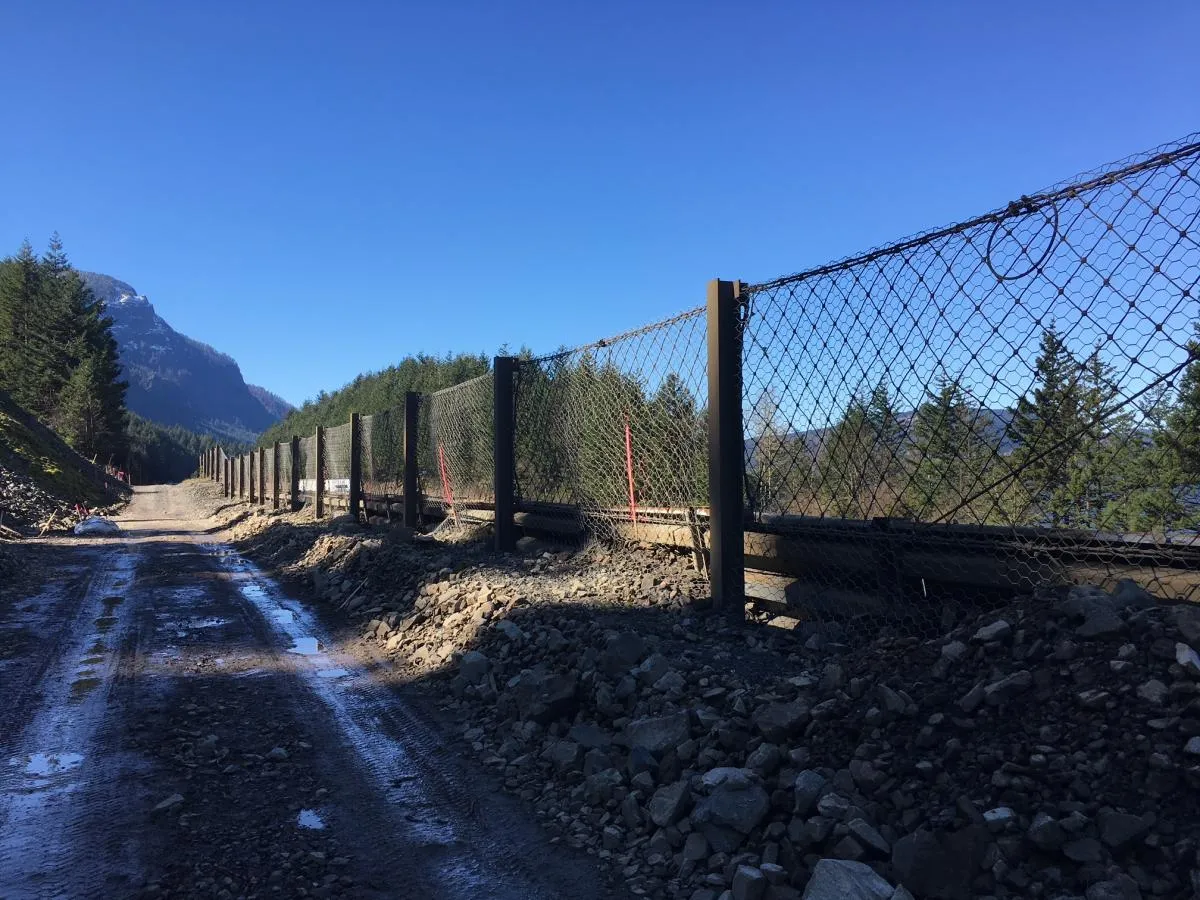
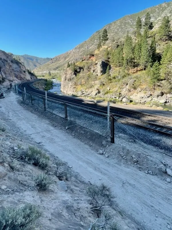
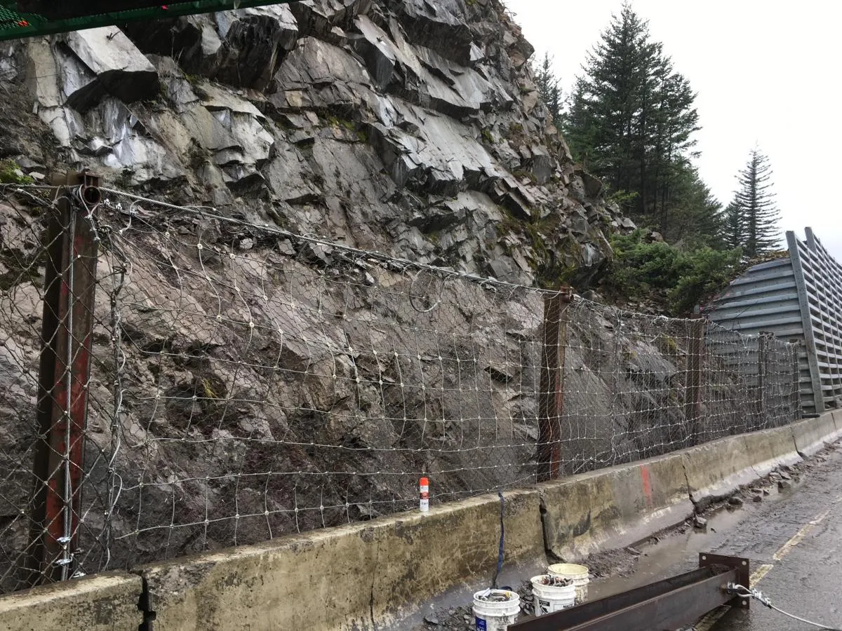
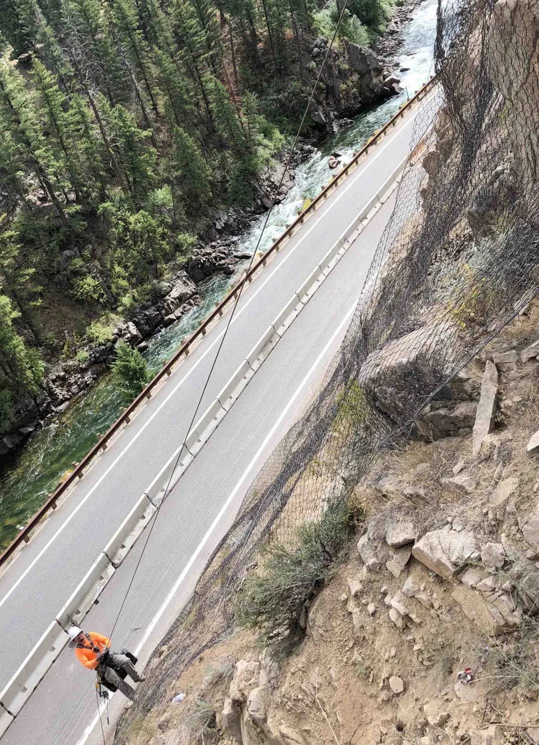
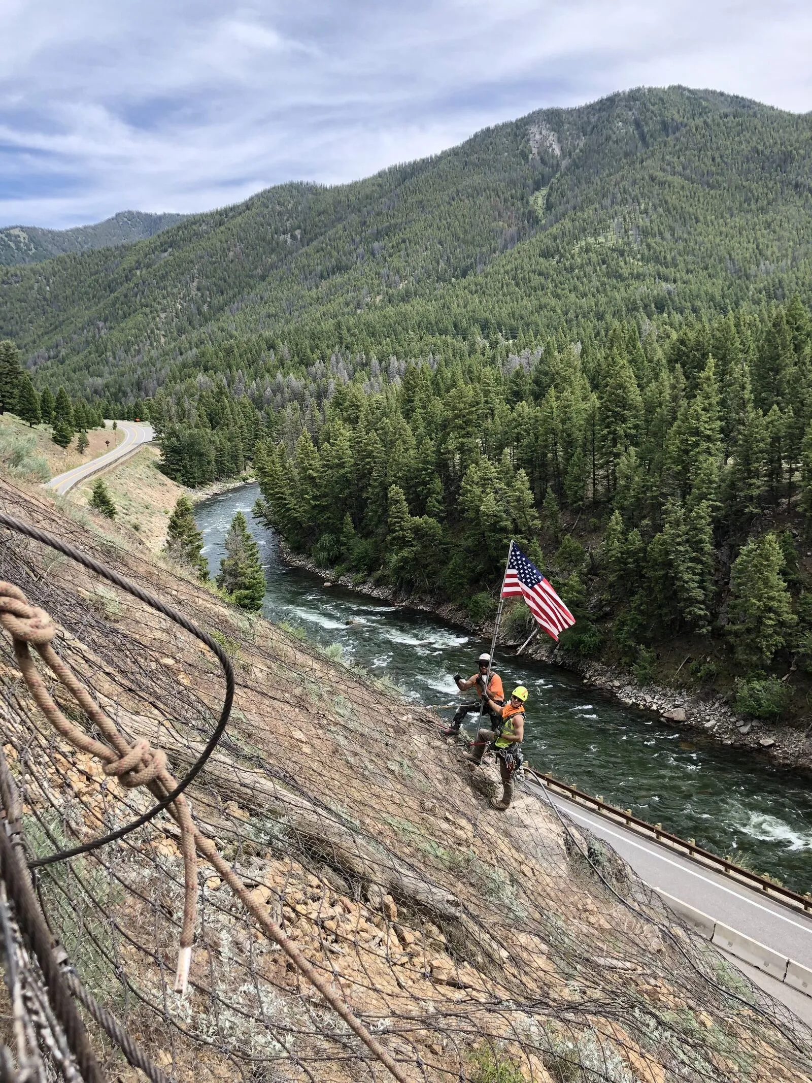
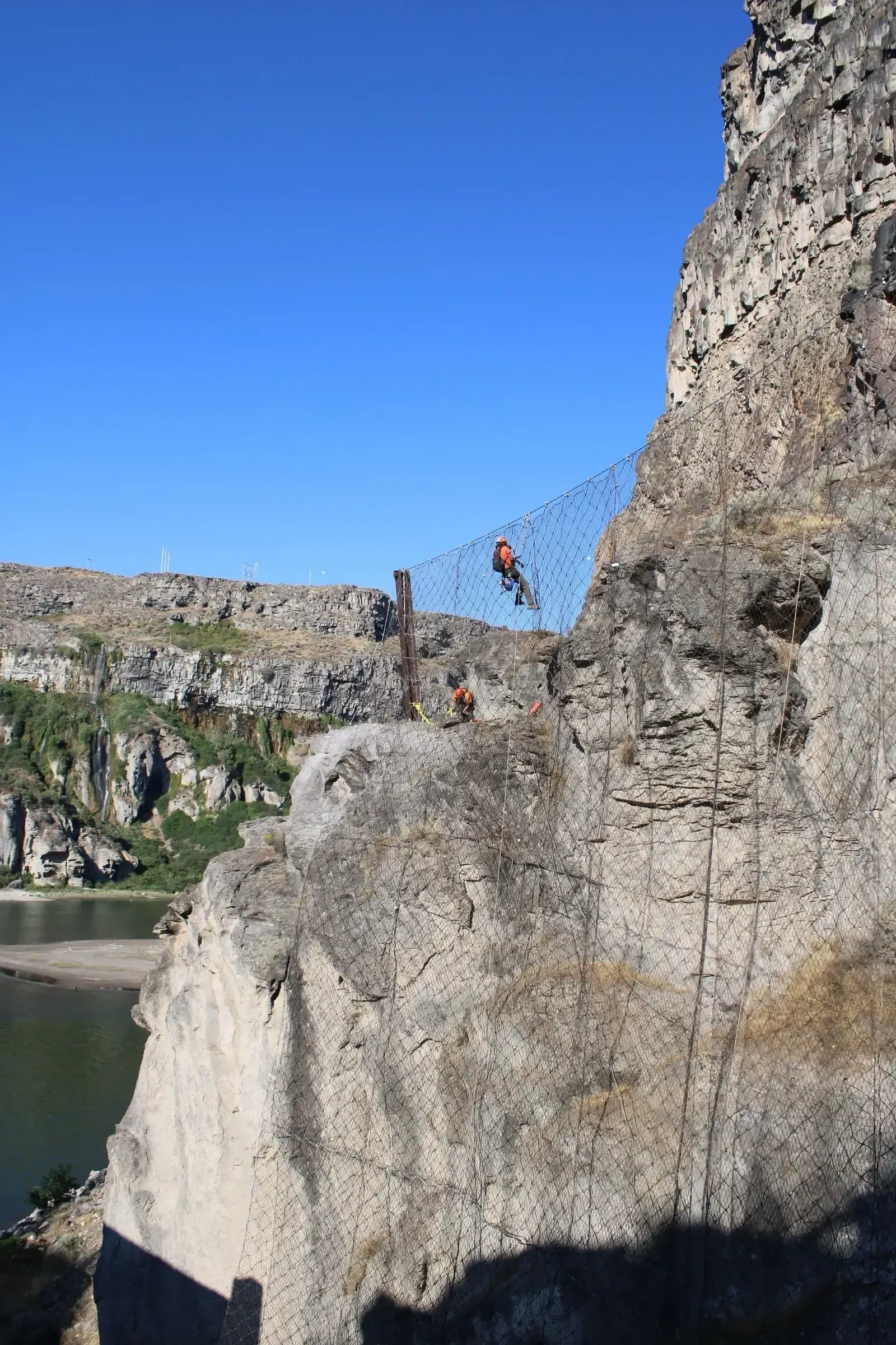
Wire-rope barriers use a woven wire-rope or cable net spanning the post array, typically rated in the 100 to 1,500 kJ range covering EAD 340059 energy classes 0 through 4. The net is built from galvanized wire-rope segments connected by ferrules or shackles, with a smaller mesh size than ring nets. Wire-rope systems are the historical default for moderate-energy roadside and rail-corridor catch fence work because the per-foot installed cost is lower than ring nets and the smaller mesh openings retain smaller blocks without requiring an interior containment liner. They remain the right tool for sites where modeled impact energy stays under roughly 1,500 kJ. The same cable-net product family is available in drape and pinned configurations on the slope face above the barrier, so a single corridor can run continuous wire-rope construction from the upper cliff face down through the toe interception line.

Type 02

Ring-Net Flexible Barriers

Ring-net barriers use interlocking steel rings (typically 250 to 350 mm ring diameter, formed from 3 to 4 mm wire) as the interception element. The ring geometry deforms progressively under impact, dissipating energy across many deformation events rather than at single failure points, and supports the highest energy classes in the certification framework. Ring nets are the modern standard for highway and rail catch fence work above roughly 1,000 kJ and extend through the EAD 340059 classes 3 through 8 to high-energy systems rated up to 10,000 kJ. The larger ring opening can pass smaller debris, so installations with mixed block sizes typically pair the ring net with a secondary fine mesh interlayer to retain the small fraction.

Type 03

Light Catch Fences and Hybrid Systems

Light catch fences are the lowest-energy variant in the family, typically 100 to 250 kJ rated and built around chain-link or hexagonal wire mesh on rigid or semi-rigid posts. They cover residential, recreational, and lower-volume corridor work where the modeled energy stays under 250 kJ and the cost premium for a flexible kit is not justified. Hybrid systems combine a flexible barrier across the post line with rigid wing-wall returns at the ends, with a draped mesh apron extending upslope from the top cable, or with a stub gabion-mass berm at the foundation toe. Hybrids appear on tall slopes where the upper hazard zone is long and the toe barrier alone cannot cover the full bounce envelope.

Side By Side

Rockfall Barrier vs Other Containment Options

VS

Rockfall Barrier vs Draped Mesh

The fundamental distinction is containment versus guidance. A rockfall barrier stops blocks at a discrete line, the deformable post-and-net array absorbs impact energy at one point in the trajectory, and the retained material drops into a designed catchment ditch immediately behind the barrier. Draped mesh hangs from a row of top anchors at the slope crest with no rigid post structure, the mesh travels with the rock surface as material releases, and it guides the falling debris downslope to a catchment area at the toe rather than stopping it in mid-air. Barriers are the right choice when bounce heights stay within the rated barrier height and a discrete catch line meets the protection target; draped mesh is the right choice when the slope is long, the source area is broadly distributed, and a continuous guidance surface beats a single catch line.

VS

Standard Rockfall Barrier vs High-Energy Barrier

Both share the same kit architecture: hinged posts, support cables, brake elements, and ring or cable net. The split is energy class. Standard rockfall barriers cover EAD 340059 classes 0 through 6, roughly 100 to 3,000 kJ, which handles the dominant volume of US highway and rail catch fence work where modeled impact energies stay in that band. High-energy barriers cover classes 7 and 8, roughly 4,500 to 10,000 kJ, and are specified where rockfall modeling produces design energies above the 3,000 kJ threshold (large blocks, tall fall heights, or long-runout slopes). High-energy systems use heavier posts, longer brake-element strokes, and more robust foundations, all of which increase per-foot installed cost meaningfully.

VS

Toe-of-Slope Barrier vs Mid-Slope Attenuator

The choice is placement strategy. A toe-of-slope rockfall barrier intercepts at the base of the slope after the rock has accelerated through its full fall, so the barrier must be sized for the worst-case impact energy at that elevation. A mid-slope attenuator intercepts partway down the slope before the rock reaches terminal velocity, dropping the impact energy a downstream barrier must absorb by roughly 50 to 70 percent. Attenuators are favored on tall slopes where the modeled toe energy exceeds available barrier capacity, on sites with constrained catchment width below the toe, or where lower-capacity barriers can be selected to control cost. Toe barriers are favored on shorter slopes, in retrofit work where mid-slope anchor access is not available, and where a single discrete catch line meets the protection target without staging.

Not sure which system fits? We'll walk through the tradeoffs for your site conditions.

Talk Through Your Options
Where It Fits

Common Applications and Project Types

Highway and interstate rock cuts are the dominant application, with state DOTs prioritizing barrier installations using the FHWA Rockfall Hazard Rating System (RHRS) developed by Pierson, Davis, and Van Vickle in 1990 to rank slopes by failure consequence and treatment cost-effectiveness. Freight and passenger rail corridors are the second major market, where barrier systems protect track from cliff-face detachments and post-storm rockfall in canyons and steep cuts. Mining haul roads and bench-face protection rely on the same kits, sized to the operational block-size envelope. Ski-area, residential canyon, and recreational-trail installations cover the lower energy classes, often in 100 to 500 kJ light catch fence and wire-rope systems. Post-event emergency installs after a documented rockfall or storm-triggered slope failure are a recurring fourth application, where a rapid barrier deployment protects the corridor while permanent rock bolting, mesh, or scaling work is designed.

Highway and interstate rock cuts
Freight and passenger rail corridors
Mining haul roads and bench faces
Ski areas and recreational trails
Post-event emergency installs after rockfall or storm
Below-cliff infrastructure protection
Codes And References

Engineering Standards and References

EOTA

EAD 340059-00-0106

Falling Rock Protection Kits

The European Assessment Document (formerly ETAG 027, 2008) governs full-scale vertical-drop impact testing and energy-class certification for flexible rockfall barriers. Defines the Service Energy Level and Maximum Energy Level test thresholds and the nine-class kJ rating system referenced by US state DOT specifications.

FHWA

FHWA-OR-EG-90-01

Rockfall Hazard Rating System

Pierson, Davis, and Van Vickle (1990) established the 12-category scoring framework that state DOTs use to prioritize rockfall mitigation, including barrier installations, against failure consequence and treatment cost. Adopted by Oregon DOT, Colorado DOT, Washington State DOT, and most US transportation agencies.

TRB

Rockfall: Characterization and Control

Turner & Schuster (eds.), 2012

The Transportation Research Board practitioner reference covering source-area mitigation, trajectory modeling, barrier and attenuator selection, draped mesh, and post-event response. Cited across DOT design manuals as the comprehensive synthesis of US rockfall practice.

Gallery

Our Work in Action

Expertise

Why Choose Rock Supremacy for Rockfall Barriers

Trajectory Modeling Support

We model rockfall energy and trajectory to specify the right barrier energy class for the slope, avoiding both under-design and unnecessary over-spec.

Difficult-Access Installation

Our rope-access crews install posts and nets on slopes and cliffs where mechanized equipment cannot operate.

Integrated Anchoring & Foundations

We drill and install rock bolts, micropiles, and concrete footings with our own crews. Post anchorage is not waiting on a subcontractor.

Emergency Mobilization

Rapid mobilization for post-event barrier installs after rockslides or storm-triggered slope failures, with temporary catch fence available before permanent kits are designed.

Certified Kit Installation

Crews trained on Geobrugg, Maccaferri, and Trumer kit assemblies per manufacturer requirements, installing to the EAD 340059 energy class on the project specification.

Questions

Rockfall Barriers & Fences FAQ

A rockfall barrier is an engineered, prefabricated catch system installed across the line of falling rock to stop and retain blocks before they strike a roadway, railway, or structure. The kit comprises foundations, hinged steel posts, upslope and lateral support cables, energy-dissipating brake elements, and a ring net or wire-rope net spanning the post array. Energy class is verified by full-scale impact test under EOTA EAD 340059-00-0106 (formerly ETAG 027), with rated capacity from 100 kJ for light catch fences up to 10,000 kJ for high-energy ring-net barriers.
The barrier absorbs impact energy through controlled deformation rather than rigid resistance. When a block strikes the net, the net deflects inward and pulls tension into the support cables. The brake elements extend through friction or ring deformation, and the residual force transfers cleanly into the foundations. Brake stroke is typically 0.5 to 2 meters, sized to match the rated Maximum Energy Level. The deformation absorbs energy progressively, holding peak load on any single component below its capacity, so the same barrier can be reset after an impact by replacing deformed brakes and damaged net panels.
ETAG 027 was the European Technical Approval Guideline for Falling Rock Protection Kits issued by the European Organisation for Technical Approvals in 2008. It was converted under the Construction Products Regulation to European Assessment Document EAD 340059-00-0106, which now controls certification for flexible rockfall barriers. The standard requires full-scale vertical-drop impact testing against two thresholds: the Service Energy Level (one-third of rated capacity, two consecutive hits, no functional damage) and the Maximum Energy Level (rated capacity, single impact, full retention). Most US state DOT specifications require EAD 340059 / ETAG 027 certification for permanent barrier installations.
The required energy class is set by rockfall trajectory modeling that combines block size, source elevation, slope geometry, and surface restitution coefficients to predict impact energy at the proposed barrier line. Typical highway catch fence work falls in the 250 to 2,000 kJ range (EAD 340059 classes 1 through 5), and most US installations are sized around the 1,000 to 3,000 kJ band. Sites with large blocks, long fall heights, or long-runout slopes can push the modeled energy above 3,000 kJ, which moves the design into the high-energy class range up to 10,000 kJ. The barrier capacity is selected with a safety factor against the modeled MEL.
A rockfall barrier stops blocks at a discrete line through a deformable post-and-net array, with retained material dropping into a catchment ditch immediately behind the barrier. Draped mesh hangs from top anchors at the slope crest with no rigid post structure, travels with the rock surface as material releases, and guides falling debris downslope to a toe catchment. Barriers are the right choice when bounce heights stay within the rated barrier height and a discrete catch line meets the protection target. Draped mesh is the right choice when the slope is long, the source area is broadly distributed, and continuous guidance is more useful than a single catch line. Many installations pair the two: draped mesh on the upper slope with a barrier at the toe.
Foundations are matched to site geology. Rock-anchored base plates with grouted bar or strand anchors are the default on competent rock outcrops where a 6 to 25 foot anchor can develop the design pullout capacity. Micropiles are used in weathered or weaker substrate where the anchor must extend deeper into competent ground or where the soil cover is too deep for a direct rock anchor. Reinforced concrete footings are used where soil cover is deep enough to support a spread foundation and rock anchors are not economic. Upslope and lateral support cables terminate in their own ground anchors set behind the line of posts, typically grouted bar or strand anchors sized to the cable design load.
Yes. The kit is engineered to be reset after an impact by replacing the deformed brake elements and any damaged net panels, while the posts, support cables, and foundations remain in service. After an event, the project team excavates the retained block from the catchment ditch, inspects the foundations and post bases for damage, replaces extended brake elements with new units of the matching specification, and re-tensions or replaces net panels as needed. Most barriers can be back in service within days of a single MEL impact and through repeated SEL hits without component replacement.
The FHWA Rockfall Hazard Rating System (RHRS) is the 12-category scoring framework developed by Pierson, Davis, and Van Vickle in 1990 (FHWA-OR-EG-90-01) that state DOTs use to prioritize rockfall mitigation against failure consequence and treatment cost. RHRS scores incorporate slope height, ditch effectiveness, average vehicle risk, percent of decision sight distance, roadway width, geological character, block size, climate and presence of water, and rockfall history. The score drives where barrier installations, scaling, mesh, and bolting investments are made first. RHRS has been adopted by Oregon, Colorado, Washington State, and most US transportation agencies, and is the upstream tool that identifies the sites where barriers are subsequently designed and installed.
Three references control US practice. EOTA EAD 340059-00-0106 (formerly ETAG 027) is the certification standard requiring full-scale impact testing against Service Energy Level and Maximum Energy Level thresholds, and is the framework state DOT specifications cite for kit selection. FHWA-OR-EG-90-01 (the Rockfall Hazard Rating System) prioritizes which slopes get barriers in the first place. Transportation Research Board, Rockfall: Characterization and Control (Turner and Schuster, eds., 2012) is the comprehensive practitioner synthesis covering trajectory modeling, source-area mitigation, barrier and attenuator selection, and post-event response.
Testimonials

Client Testimonials

Trusted by DOTs, engineering firms, and property owners nationwide.

Contact

Deploy Us

Ready to discuss your project? Our team is standing by to assess your site conditions and develop a custom solution using Rockfall Barriers & Fences and other proven techniques.

Emergency (24/7)

(541) 383-7625

Bidding & Estimates

Info@RockSupremacy.com

Headquarters

Western Division (HQ)
65147 N Hwy 97
Bend, OR 97701
Eastern Division
915 Millennium Ct
Blountville, TN 37617

Licensed in CO, UT, WY, ID, MT, CA, WA, OR, TN, VA

Request Consultation