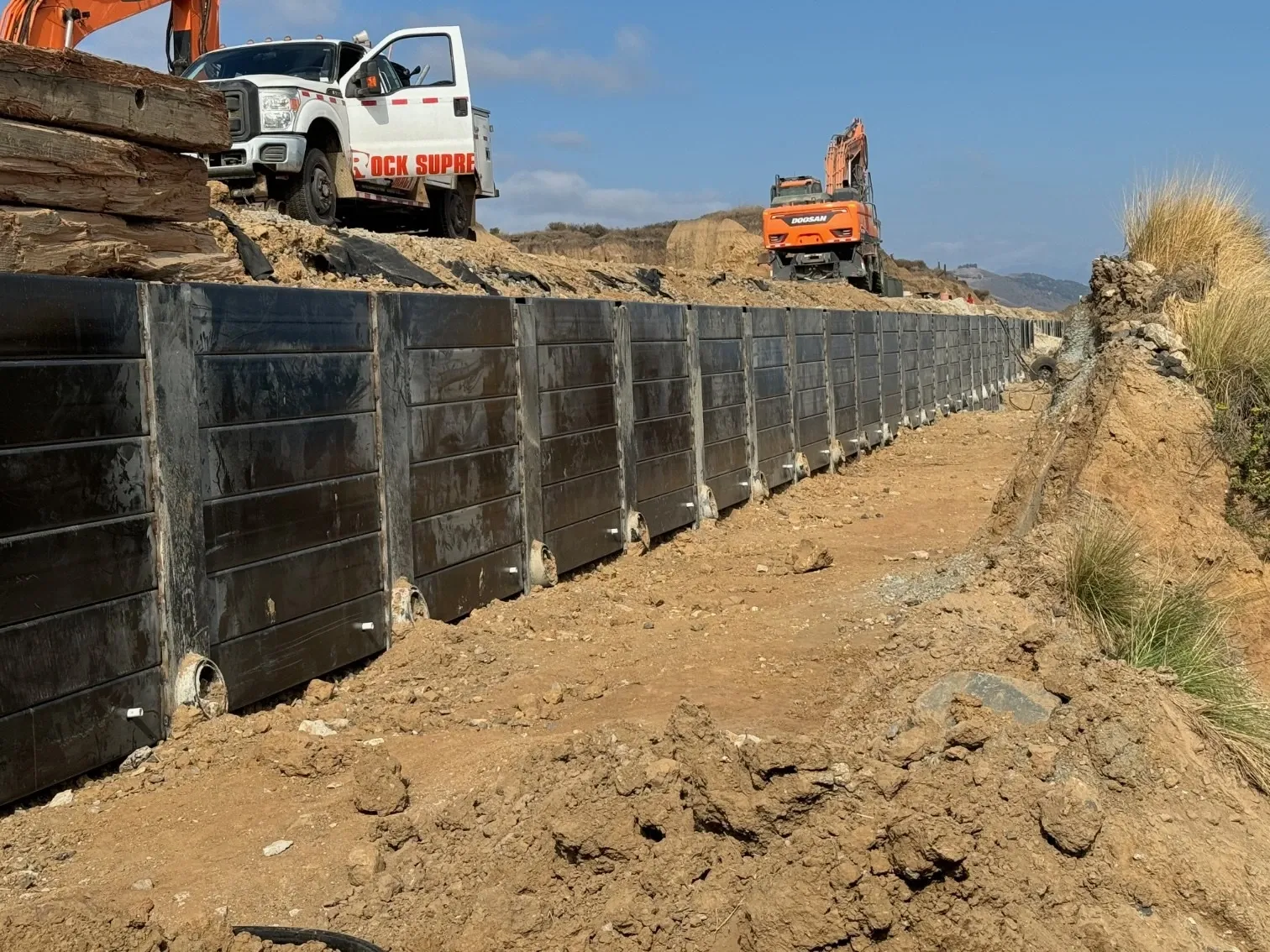
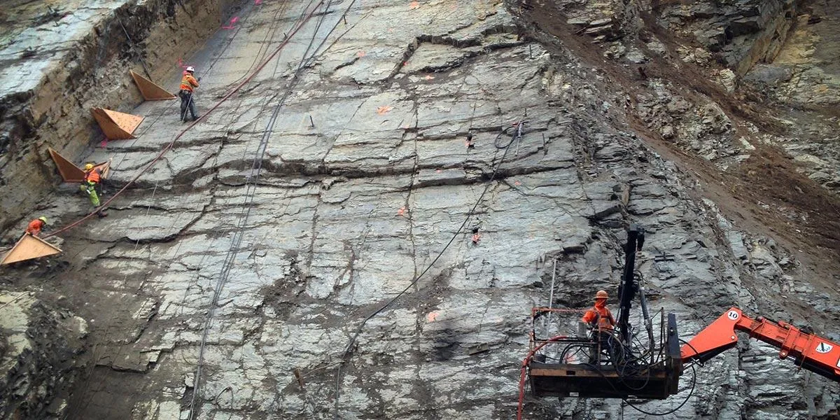
Steel Plate & Shotcrete Lagging

Steel Plate & Shotcrete Lagging

Lagging systems span between soldier piles using steel plates, timber, or shotcrete to retain soil during excavation. The choice of lagging material affects installation speed, cost, permanence, and aesthetic finish.

10 ft
Max Span
6 in
Shotcrete Thickness
1 in
Steel Plate Thickness
75+ yr
Permanent Life
Overview

Understanding Steel Plate & Shotcrete Lagging

Lagging is the horizontal spanning element in soldier pile wall systems, transferring lateral earth pressure from the retained soil to the vertical piles. As excavation proceeds in lifts, lagging is installed between pile flanges to prevent soil from collapsing into the excavation.

Steel plates provide rapid temporary installation. Timber lagging offers economy for standard applications. Shotcrete lagging creates monolithic structural walls suitable for permanent applications with architectural finishing potential. The right lagging choice depends on wall permanence, load requirements, groundwater conditions, and project constraints.

Rapid installation keeps pace with excavation
Accommodates utilities and obstructions in soil
Flexible for irregular excavation geometries
Multiple material options for different applications
Can be temporary or permanent
Works with tiebacks, bracing, or rakers
Cost-effective for many excavation depths
Familiar system with extensive contractor experience

This technique is used in our services for:

Steel Plate & Shotcrete Lagging
Use Cases

Typical Applications

Building basement excavations
Utility corridor protection
Bridge abutment construction
Urban infill site excavations
Highway cut sections
Railroad grade separations
Parking structure excavations
Industrial facility foundations
Steel Plate & Shotcrete Lagging - Image 1
Process

How It Works

Our proven methodology ensures consistent, high-quality results for every installation.

1

Soldier Pile Installation

Drive or drill soldier piles (H-beams or wide-flange sections) at design spacing, typically 6-10 feet on center. Pile size and spacing determine lagging span and required thickness.

2

Initial Excavation

Excavate soil in controlled lifts (typically 4-5 feet) between pile rows. Maintain stable excavation face during each lift. Excavation must not proceed below the lowest installed lagging level.

3

Lagging Installation

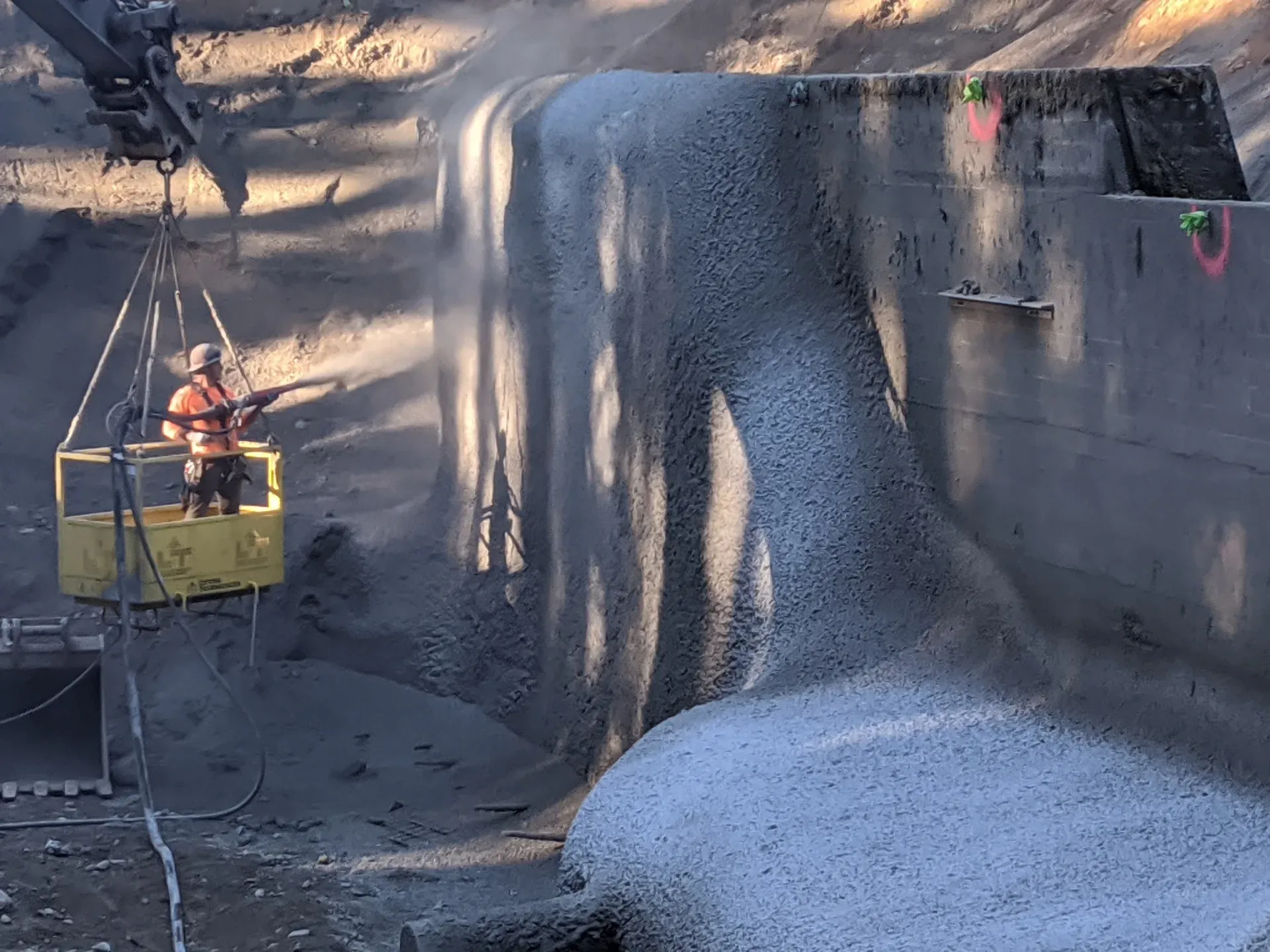
Install lagging material between pile flanges immediately after each excavation lift. For steel plates, slide into pile flanges. For timber, wedge between flanges. For shotcrete, install drainage mat, reinforcement, and apply shotcrete against soil face.

4

Backpacking

Fill voids between lagging and soil face with pea gravel, lean concrete, or controlled low-strength material. Backpacking ensures uniform load transfer and prevents point loading on lagging.

5

Tieback or Bracing Installation

At design elevations, drill through or between lagging panels to install tieback anchors. Install waler beams across pile flanges to distribute anchor loads. Stress tiebacks before continuing excavation.

6

Wall Completion

Continue excavation and lagging installation to final grade. For permanent walls, apply architectural facing, waterproofing, or additional shotcrete layers. Install drainage systems behind finished wall.

Benefits

Key Advantages

Installation Speed

Lagging installs as excavation proceeds with minimal delay. Well-coordinated crews can excavate and lag significant wall lengths daily, keeping construction schedules on track.

Material Flexibility

Choose lagging material based on project needs: steel for speed, timber for economy, shotcrete for permanence. Different materials can even be used on the same wall for different conditions.

Obstruction Tolerance

Unlike continuous wall systems, lagging can be adjusted around utilities, boulders, and other obstructions. Modified panels or local shotcrete filling address irregularities without redesigning the entire wall.

Architectural Potential

Shotcrete lagging accepts architectural treatments including integral color, form-lined textures, and decorative coatings. Permanent basement walls can be aesthetically finished rather than hidden.

Groundwater Management

Drainage mats and weep systems behind lagging control groundwater infiltration. Shotcrete lagging with proper drainage creates dry basement walls suitable for occupied spaces.

Engineering

Technical Considerations

Soil/Rock Conditions

Lagging design depends on soil type and earth pressure. Soft clays may require closer pile spacing or thicker lagging. Granular soils stand better between lifts, allowing longer lagging panels. Rock faces may need only spot bolting.

Groundwater

Lagging systems are not inherently watertight. Install drainage composite behind lagging to collect and direct groundwater to weep drains. In high water conditions, combine with dewatering or use sheet pile cutoff below lagging zone.

Load Capacity

Lagging spans between piles as a simple beam. Earth pressure, surcharge loads, and hydrostatic pressure (if not drained) determine required thickness. Longer spans require thicker lagging or supplemental support.

Spacing

Typical 6-8 foot pile spacing balances economy with lagging requirements. Wider spacing (8-10 feet) suits shallow excavations in competent soils. Closer spacing (4-6 feet) handles soft soils, heavy surcharge, or high groundwater.

Installation Method

Steel plates slide into pile flanges with minimal excavation exposure. Timber wedges into place with hand tools. Shotcrete requires drainage mat installation, reinforcement placement, and nozzle access—needs more working room but creates continuous wall.

Equipment Used

  • Excavators for soil removal
  • Cranes or forklifts for material handling
  • Shotcrete pumps and nozzles
  • Compressors for shotcrete application
  • Tieback drilling rigs
  • Stressing equipment for anchors

Limitations

  • Not watertight without supplemental drainage or dewatering
  • Timber lagging has limited fire resistance
  • Steel plates may require welding for permanent applications
  • Shotcrete requires skilled nozzlemen and curing time
  • Limited to soldier pile wall configurations

Technical Specifications

Steel Plate Thickness
3/8 to 1 inch
Timber Lagging
3x12 to 4x12 lumber
Shotcrete Thickness
4-6 inches typical
Typical Span
6-10 ft between piles
Reinforcement
WWM or fiber (shotcrete)
Earth Pressure Design
Active to at-rest
Options

System Variations

Steel Plate Lagging

Steel plates (3/8 to 1 inch thick) slide between soldier pile flanges for immediate support. Fast installation, reusable on temporary walls, and suitable for high earth pressures. Often left in place on permanent walls.

Best For:

  • Fast-track construction
  • Temporary excavation support
  • High-load conditions
  • Reusable shoring systems

Timber Lagging

Dimensional lumber (typically 3x12 or 4x12) wedged horizontally between pile flanges. Most economical option for routine excavations. Usually left in place and buried during backfill or permanent wall construction.

Best For:

  • Cost-sensitive projects
  • Temporary walls
  • Moderate depths
  • Standard soil conditions

Shotcrete Lagging

Reinforced shotcrete applied directly against the excavation face, encasing pile flanges. Creates monolithic permanent wall with architectural finish potential. Requires drainage mat and reinforcement installation before application.

Best For:

  • Permanent basement walls
  • Architectural exposure
  • Irregular excavation faces
  • Long-term service

Precast Concrete Lagging

Factory-produced concrete panels installed between pile flanges. Combines permanence of concrete with speed of prefabrication. Higher quality control than field-applied shotcrete.

Best For:

  • Permanent walls requiring consistent finish
  • Projects with repetitive panel sizes
  • Quality-critical applications
Experience

Example Project Types

  • Commercial building basements
  • Residential foundation excavations
  • Underground parking structures
  • Utility vault construction
  • Bridge abutment and wing walls
  • Transit station excavations
  • Industrial facility foundations
  • Urban infill development
Gallery

Our Work in Action

Expertise

Why Choose Rock Supremacy for Lagging Systems

Complete Wall Construction

We install the entire soldier pile and lagging system—piles, lagging, tiebacks, and drainage. Single-source responsibility means coordinated installation and clear accountability.

Shotcrete Expertise

Our ACI-certified nozzlemen apply shotcrete lagging that meets structural and aesthetic requirements. We handle exposed permanent walls with the quality they demand.

Adaptive Approach

We select lagging materials based on your project needs, not what's convenient for us. Steel, timber, or shotcrete—we recommend and install what works best for your specific conditions.

Urban Experience

Our crews understand working in tight urban sites with utilities, adjacent buildings, and access constraints. We coordinate lagging installation with ongoing site operations.

Schedule Performance

Lagging must keep pace with excavation. Our experienced crews and material logistics ensure lagging never delays your excavation progress.

Questions

Steel Plate & Shotcrete Lagging FAQ

Steel plate lagging installs faster, handles higher loads, and is reusable on temporary walls. Timber lagging costs less and works well for moderate loads and standard conditions. Steel is preferred for fast-track projects, deep excavations, or high surcharge. Timber suits routine basements and budget-conscious projects.
Specify shotcrete lagging when the wall will be permanently exposed (basements, parking structures), when architectural finish is important, when the excavation face is irregular, or when long-term durability matters. Shotcrete also works well where utilities or obstructions require filling around irregular shapes.
We install drainage composite (geocomposite or drainage mat) behind lagging to collect infiltrating groundwater. Weep drains at the wall base discharge collected water. For heavy groundwater, we may combine drainage with dewatering wells or sumps. Proper drainage prevents hydrostatic pressure buildup that could overload the wall.
Yes. Shotcrete lagging with proper reinforcement and drainage creates permanent walls with 75+ year design life. Steel plates can be welded in place and coated for permanence. Even timber lagging can be encased in cast-in-place concrete for permanent construction, though this is less common.
Steel and timber lagging install immediately as excavation proceeds—typically 50-100 linear feet of wall face per day depending on pile spacing and conditions. Shotcrete lagging requires more time for drainage mat and reinforcement installation plus curing, but skilled crews can still shotcrete 30-50 feet of wall per day.
Testimonials

Client Testimonials

Trusted by DOTs, engineering firms, and property owners nationwide.

Contact

Deploy Us

Ready to discuss your project? Our team is standing by to assess your site conditions and develop a custom solution using Steel Plate & Shotcrete Lagging and other proven techniques.

Emergency (24/7)

(541) 383-7625

Bidding & Estimates

Info@RockSupremacy.com

Headquarters

Western Division (HQ)
65147 N Hwy 97
Bend, OR 97701
Eastern Division
915 Millennium Ct
Blountville, TN 37617

Licensed in CO, UT, WY, ID, MT, CA, WA, OR, TN, VA

Request Consultation