Soil Nailing

Soil Nailing

Steel bars driven into soil to reinforce and stabilize loose ground or slope faces.

Bar Types
Solid Bar / Hollow Core
Drill Angle
10° to 20° Declination
Face Finish
Shotcrete / Mesh / Vegetation
Bond Strength
Dependent on Soil Type
Overview

Understanding Soil Nailing

Soil nailing is a top-down earth retention technique that reinforces an existing slope or excavation face with a closely spaced grid of grouted steel bars, allowing what would otherwise be an unstable cut to stand vertically or near-vertically as a permanent wall. From an engineering standpoint, the system creates a passive, in-situ composite reinforced soil mass that behaves as a single coherent gravity structure, with tension developing in the bars only as the surrounding ground attempts to deform. Soil nail walls are widely deployed on highway and interstate cuts, building excavation shoring, landslide repair, slope stabilization on steep terrain, and rail corridor reconstruction.

What Is Soil Nailing?

Soil nailing was developed at the Versailles railroad cut in France in the early 1970s as an adaptation of the New Austrian Tunneling Method to open-cut earthwork. The technique entered mainstream US practice through Federal Highway Administration demonstration projects and reference manuals beginning in the 1990s, and is now a codified retaining wall option in AASHTO and state DOT design manuals. A soil nail wall is not a structural wall in the conventional sense. The reinforced soil mass itself acts as the retaining structure, behaving as a coherent gravity wall that resists external loads through its mobilized weight and internal shear strength.

Three component systems work together. The nails are steel bars surrounded by a continuous grout column that develops tensile capacity through bond between the bar and the grout, and bond between the grout and the surrounding ground. The facing is typically structural shotcrete reinforced with welded wire mesh, anchored to the nail heads through bearing plates and nuts. The drainage system, generally chimney drains or geocomposite strips placed against the cut face before shotcreting, prevents hydrostatic pressure from accumulating behind the wall.

Key Benefits

  • Allows top-down construction
  • Equipment accessible in tight spaces
  • Cost-effective vs tie-backs
The Engineering

How Soil Nailing Works

How the system carries load in service, and how we build it on site.

Construction proceeds top-down in lifts. A 4 to 6 foot lift is excavated across the wall footprint, exposing a fresh vertical or battered face. Nails are then drilled on a roughly 4 to 6 foot grid at a downward inclination of 10 to 20 degrees, with 15 degrees serving as the FHWA default. A solid or hollow steel bar is inserted with centralizers to maintain grout cover, and cement grout is placed in the annular space between the bar and the borehole wall. Drainage strips and welded wire mesh are installed against the face, and a structural shotcrete facing is shot to the design thickness. The crew advances to the next lift and the sequence repeats to final grade.

Load transfer follows a clear path. Lateral earth pressure pushes outward against the shotcrete facing, which transfers load through bearing plates into the nail heads. The nails carry that load in tension, and the tension is resisted by friction, with some passive bearing on deformed bar lugs, mobilized along the grouted column behind the active failure surface. Because the nails are distributed across the wall face rather than concentrated at discrete points, the reinforced volume of soil behaves as a single coherent gravity wall.

1

Excavation

Top-down excavation in 5-6ft lifts.

2

Drilling

Drilling nail holes at specified angle and spacing.

3

Install & Grout

Inserting nail and grouting the annular space.

4

Facing

Applying shotcrete or mesh to connect nail heads.

System Variants

Types of Soil Nails

Type 01

Drilled-and-Grouted Solid Bar Nails

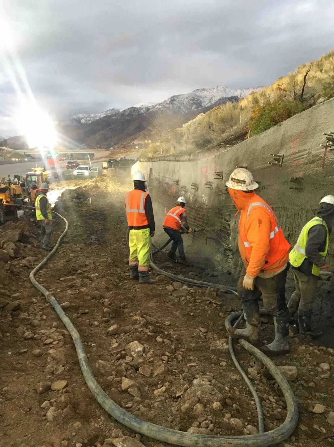
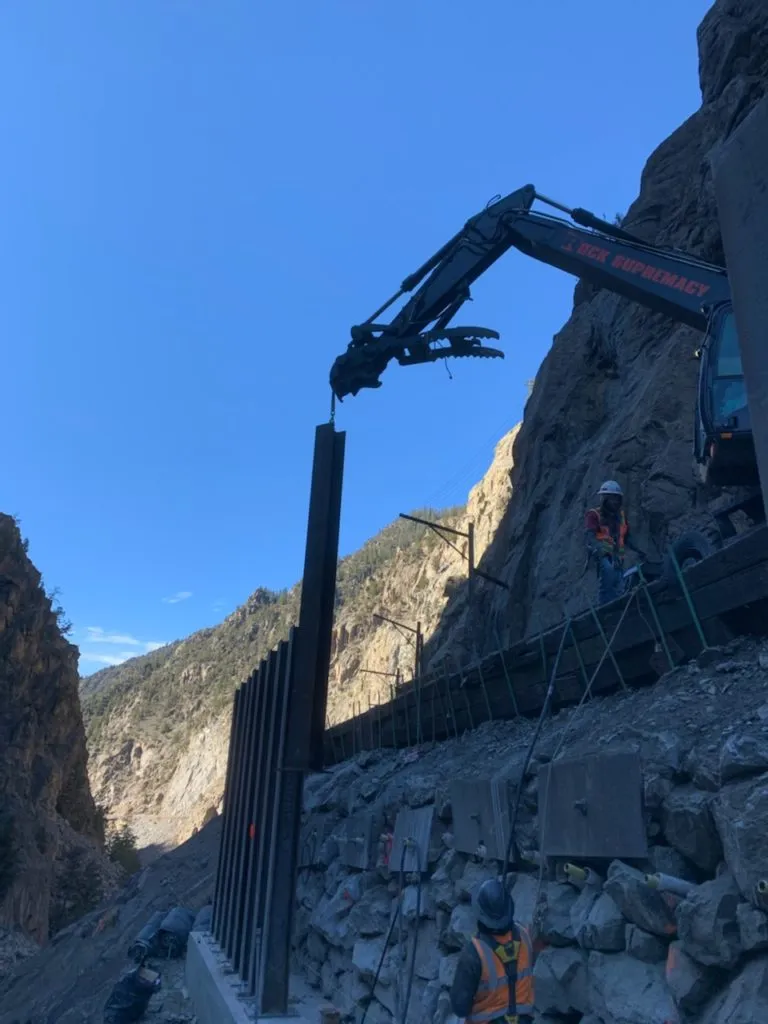
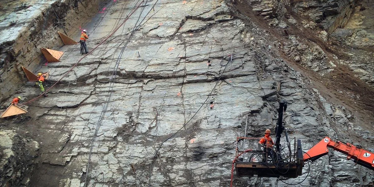
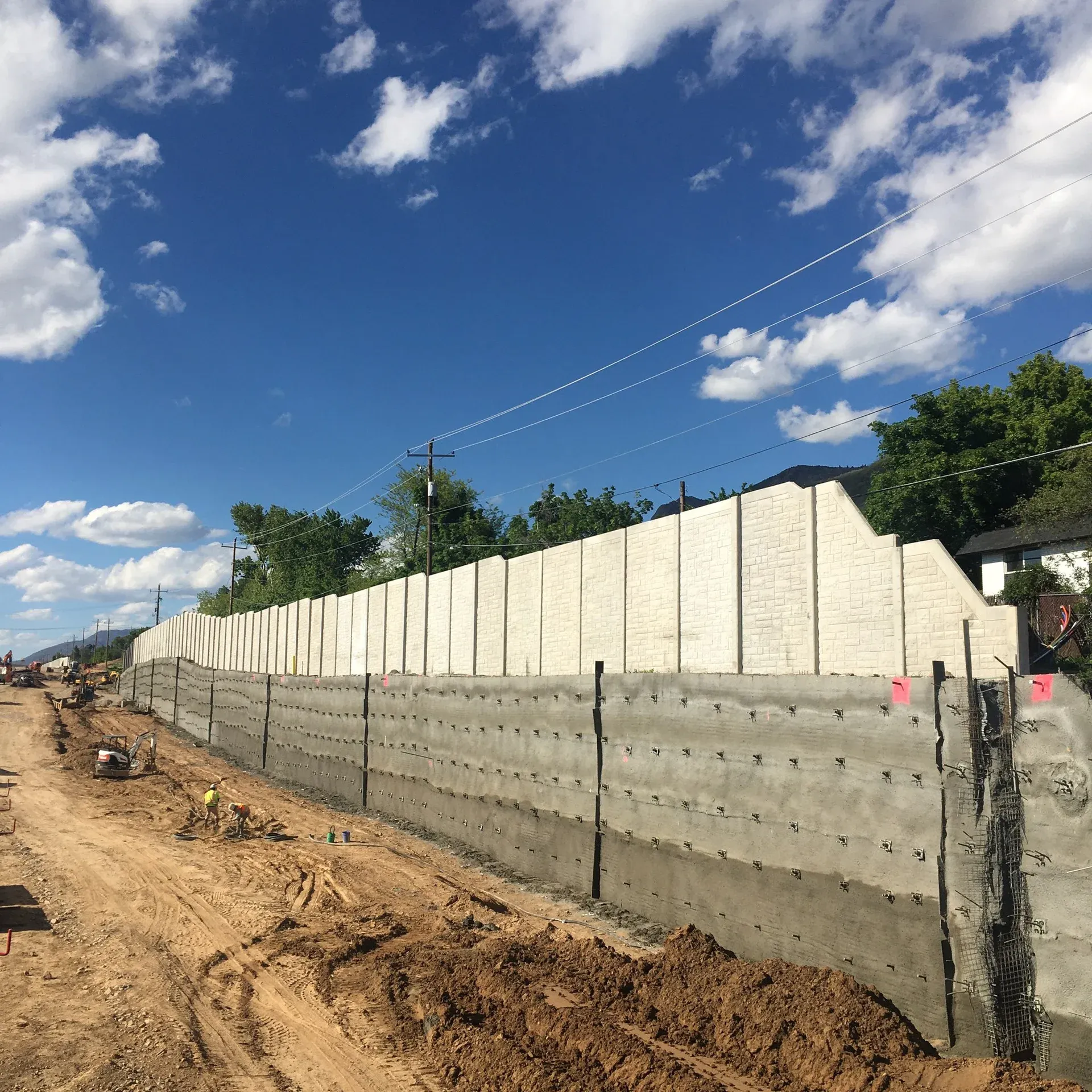
Drilled-and-grouted nails are the most common nail type used on stable, self-supporting ground. Installation is a two-stage process: a borehole is advanced with rotary or rotary-percussive drilling equipment, a solid threaded bar is inserted with centralizers, and neat cement grout is placed by tremie line from the toe of the hole upward. Cost per linear foot is lower than self-drilling alternatives, which makes solid bar nails the default selection on highway cut projects in competent soils. The limiting factor is the open-hole interval between casing withdrawal and grouting, which restricts use in soils that will not stand open.

Type 02

Hollow-Core Self-Drilling Nails

Self-drilling nails use a hollow steel bar that doubles as the drill rod, with a sacrificial drill bit threaded onto the toe. Grout is pumped through the bar during drilling, both flushing cuttings out of the hole and forming the grout column in a single pass. Eliminating the open-hole interval makes hollow-core nails the system of choice in collapsing, running, or otherwise structureless ground, including most landslide-repair work where the soil mass has already lost cohesion. Cost per linear foot is meaningfully higher than drilled-and-grouted, and galvanized hollow bars are common for permanent applications where corrosion protection is required.

Type 03

Driven and Launched Nails

Driven nails are installed by impact or vibratory hammers without grout, relying on direct mechanical contact between the bar and the soil for load transfer. Their bond capacity is low, and they appear almost exclusively in temporary or low-load installations rather than permanent walls. Launched nails are propelled at high velocity from a compressed-air gun, typically in lengths of 20 feet or more, and are specified for emergency rockfall stabilization and short-duration slope reinforcement after a failure. Both systems carry materially lower bond capacity than grouted nails and are written into specifications narrowly, on a project-by-project basis.

Side By Side

Soil Nail Walls vs Other Retaining Wall Systems

VS

Soil Nail Wall vs MSE Wall

The fundamental distinction is cut versus fill. A soil nail wall reinforces undisturbed in-situ ground from the top down as the cut is advanced, while an MSE walls system retains a controlled, imported select backfill placed bottom-up on a prepared foundation. The geometry of the project, not the price, usually drives the selection. When a roadway widening or a building pad requires cutting into an existing slope or hillside, soil nailing is the right tool. When the alignment requires building an embankment up from grade, an MSE wall is the right tool. At moderate wall heights the installed cost per square foot of face is roughly comparable between the two systems, so engineers should let the cut-versus-fill condition decide.

VS

Soil Nail Wall vs Soldier Pile Wall

Both systems are constructed top-down, but the load mechanisms differ sharply. A soil nail wall reinforces the entire soil mass with closely spaced nails that engage the ground continuously across the face, while soldier pile walls concentrate the lateral load at discrete vertical steel beams set in drilled shafts, with timber or concrete lagging spanning between piles. Soil nail walls typically come in 25 to 50 percent cheaper than soldier pile walls at equivalent height. Soldier pile walls are preferred where the excavation behind the wall must remain open for utility access, deeper tieback installation, or cut-and-cover construction, since the soil nail grid forecloses any future intrusion into the reinforced zone.

VS

Soil Nail Wall vs Tieback Anchor Wall

The defining difference is passive versus active reinforcement. Soil nails carry no preload at installation and develop tension only as the soil tries to move outward, while tieback anchors are post-tensioned against the wall facing and load the ground at install. Capacity differs by an order of magnitude. Tieback anchors typically carry 100 to 600 or more kips per anchor, where a single soil nail typically develops 15 to 60 kips. Geometrically, tiebacks have an unbonded free length plus a bonded fixed length seated deep in stable ground, while soil nails are bonded over their full length. Tall hybrid walls often combine the two, using tiebacks at the upper portion where loads concentrate and soil nails through the rest of the face.

Not sure which system fits? We'll walk through the tradeoffs for your site conditions.

Talk Through Your Options
Where It Fits

Common Applications and Project Types

Highway and interstate cut slopes account for the dominant application volume, with state DOTs and AASHTO-governed projects driving the majority of permanent soil nail wall construction in the United States. Beyond highway work, the technique is heavily used for commercial and industrial excavation shoring, including basement and foundation cuts in dense urban sites, and for post-failure landslide repair where rapid stabilization is required. Rail corridor reconstruction, bridge abutment retention behind cast-in-place footings, and mining haul road and high-wall stabilization round out the typical project mix. Owners selecting a soil nailing contractor should confirm that crews have demonstrable experience in the specific application class, since means and methods vary materially.

Retaining walls
Highway widening
Bridge abutments
Codes And References

Engineering Standards and References

FHWA

NHI-14-007

Soil Nail Walls Reference Manual

The canonical practitioner document covering geotechnical analysis, structural design, corrosion protection, and construction inspection. Cited by virtually every state DOT specification.

AASHTO

LRFD §11.12

Bridge Design Specifications

Provides load and resistance factors and the design life framework for permanent soil nail walls on transportation projects.

ACI

506

Shotcrete Facing Standard

Covers shotcrete materials, mix design, application, and placement requirements for the structural facing on soil nail walls.

Gallery

Our Work in Action

Questions

Soil Nailing FAQ

A soil nail is a slender, tension-resisting steel reinforcing bar, typically a #6 to #11 deformed rebar, an epoxy-coated bar, or a hollow self-drilling bar, installed into in-situ soil at a downward angle of about 10 to 20 degrees and bonded to the surrounding ground with cement grout. Once a grid of nails is connected by a structural shotcrete or concrete face, the reinforced soil mass behaves as a coherent gravity-retaining structure. Unlike tieback anchors, soil nails are passive: they develop tension only as the surrounding soil tries to move, rather than being pre-stressed at install.
Soil nailing works by reinforcing in-situ ground top-down as excavation proceeds. A 4 to 6 foot lift is cut, near-horizontal holes are drilled into the exposed face on a roughly 4 to 6 foot grid, a steel bar with centralizers is inserted, the annular space is grouted, drainage strips and welded wire mesh are placed, and a structural shotcrete face is shot to engage the nail heads with bearing plates. The pattern repeats for each successive lift. The finished wall transfers lateral earth pressure from the face into the nail array, which carries it as tension into competent soil behind the active failure surface.
A soil nail is installed in soil or weathered rock, is fully grouted along its length, is passive (develops load only when the ground moves), and is typically 15 to 60 feet long. A rock bolt is installed in competent rock, can be either fully grouted or end-anchored, can be either passive or actively pre-tensioned, and is typically shorter, 6 to 25 feet, because rock develops load resistance faster than soil. The choice usually follows the ground type: nails for soil cuts and weathered rock, bolts for jointed competent rock slopes and tunnels.
Both are drilled, grouted, ground-reinforcement elements, but they differ on three axes. First, tiebacks are pre-tensioned (active), while soil nails carry no preload (passive). Second, tiebacks have an unbonded free length plus a bonded fixed length deep in stable ground, allowing the bar to stretch elastically. Soil nails are bonded over their full length. Third, tieback anchors can carry 100 to 600 plus kips per anchor, while soil nails typically work in the 15 to 60 kip range. Tall walls often combine the two, tiebacks at the top where loads concentrate, soil nails through the rest of the face.
Soil nails are typically 15 to 60 feet long, with 30 to 40 feet being the most common range for highway and commercial cuts. Length is set during design as a function of wall height, soil shear strength, surcharge loading, and the geometry of the active failure surface. Soil nails must extend well behind that surface into the resistant zone to be effective. Nails on a tall wall or in low-strength soil may exceed 60 feet. Nails on a short residential cut in stiff clay may be as short as 12 to 15 feet. Length and spacing are paired in design, with denser spacing allowing shorter nails.
Soil nails are installed on a downward inclination of roughly 10 to 20 degrees below horizontal, with the FHWA-default design angle being 15 degrees. The downward angle ensures the grout fills the hole completely under gravity (preventing voids), aligns the nail with the principal tensile direction in the soil mass behind the wall, and crosses potential failure surfaces at an effective angle. Steeper angles up to 25 degrees are used in specific cases, for example to navigate around utilities or to extend nails into deeper competent soil, but very steep nails lose efficiency in resisting horizontal earth pressure.
Drilled-and-grouted (solid-bar) soil nails are installed in two stages: a casing is drilled into the ground with rotary or rotary-percussive equipment, the casing is withdrawn while a solid steel bar is inserted, and cement grout is then placed via a tremie line. Self-drilling (hollow-core) nails combine drilling and grouting into a single pass: the hollow bar itself acts as the drill rod, a sacrificial drill bit is left at the toe, and grout is pumped through the bar during drilling. Self-drilling nails install faster in collapsing or running ground but cost more per linear foot. Solid-bar nails are typically lower cost in stable ground.
In the United States, soil nail wall design follows three primary references. FHWA Publication NHI-14-007, the Soil Nail Walls Reference Manual, is the canonical practitioner document covering geotechnical analysis, structural design, corrosion protection, and construction inspection. AASHTO LRFD Bridge Design Specifications, Section 11.12, defines load and resistance factors and minimum design life for transportation projects. ACI 506 governs the shotcrete facing. State DOT specifications typically reference these documents and add jurisdiction-specific testing and corrosion-protection requirements.
Testimonials

Client Testimonials

Trusted by DOTs, engineering firms, and property owners nationwide.

Contact

Deploy Us

Ready to discuss your project? Our team is standing by to assess your site conditions and develop a custom solution using Soil Nailing and other proven techniques.

Emergency (24/7)

(541) 383-7625

Bidding & Estimates

Info@RockSupremacy.com

Headquarters

Western Division (HQ)
65147 N Hwy 97
Bend, OR 97701
Eastern Division
915 Millennium Ct
Blountville, TN 37617

Licensed in CO, UT, WY, ID, MT, CA, WA, OR, TN, VA

Request Consultation

Methods

Related Techniques

Explore other engineering methods we use to deliver comprehensive geotechnical solutions.

Blasting & Boulder Busting
Blasting & Boulder Busting icon

Blasting & Boulder Busting

Rock blasting uses engineered explosive charges to fragment rock for excavation, slope correction, hazard removal, and access development. Production, pre-split, and smooth-wall methods deliver fragmentation while keeping ground vibration, airblast, and flyrock within regulatory limits.

Learn More
Cable Anchors
Cable Anchors icon

Cable Anchors

Cable anchors are post-tensioned multi-strand prestressed anchors that drill deep into competent rock or dense soil, develop bond along a fixed-length zone, and are stressed to lock in 200 to 2000 plus kips of holding load. They are the high-capacity end of the post-tensioned ground anchor family, used for dam abutment stabilization, large rock-mass tie-down, deep landslide remediation, and the foundation anchoring of high-energy rockfall barriers.

Learn More
Sculpted Shotcrete Finishes
Sculpted Shotcrete Finishes icon

Sculpted Shotcrete Finishes

Sculpted shotcrete is structural shotcrete carved in the plastic state to replicate natural rock, dry-stacked stone, or custom architectural textures, then stained with iron oxide pigments and sealed for UV-stable, weather-resistant aesthetics. The system pairs full ACI 506 structural capacity with engineered finish work for highway slope facings, retaining walls, theme park rockwork, and architectural civil features.

Learn More
Debris Flow Barriers
Debris Flow Barriers icon

Debris Flow Barriers

Engineered catch systems installed across drainage channels to retain post-wildfire and torrent debris flows. Flexible ring-net kits absorb a fluidized surge plus boulder impact through brake-element deformation, with a basal opening that passes normal water and sediment between events.

Learn More