High-energy barrier design starts with the same trajectory modeling as any rockfall barrier, but the inputs that drive a high-energy specification are distinctive: design block masses in the 1 to 5+ tonne range, fall heights typically above 200 feet, and slopes long enough that bounce velocities approach terminal. The modeled MEL at the proposed catch line is matched against the EAD 340059 class table, and any modeled energy above 3,000 kJ moves the design out of the standard class range and into Class 7 (4,500 kJ) or Class 8 (8,000 to 10,000+ kJ). Selection includes a safety factor against the modeled MEL, typically requiring kit capacity 1.2 to 1.5 times the predicted impact.
On the ground, the energy path through the kit is the same as a standard barrier but the strokes and loads are larger. The block engages the ring net, the net deflects inward, and the deflection pulls tension into upslope and lateral support cables. The brake elements extend through controlled deformation across the longer 2 to 3+ meter stroke required to absorb a Class 7-8 impact, holding peak load on every component below its capacity. The residual force transfers through the cables and post bases into engineered foundations, typically rock-anchored base plates with paired grouted bar or strand anchors on competent rock, micropiles socketed into competent ground in weathered or weaker substrate, or reinforced concrete footings with deeper embedment than a standard barrier requires. The brake stroke and foundation sizing are the two design choices that most distinguish a high-energy barrier from a standard one.
1
Trajectory Analysis and Class Selection
Rockfall modeling sets design block size, MEL at the catch line, and the EAD 340059 energy class. Output drives kit selection, post height, and barrier alignment.
2
Foundation Engineering
Paired rock anchors, micropile clusters, or reinforced concrete footings sized for Class 7-8 dynamic loads, with embedment and capacity verified by site geotechnical investigation.
3
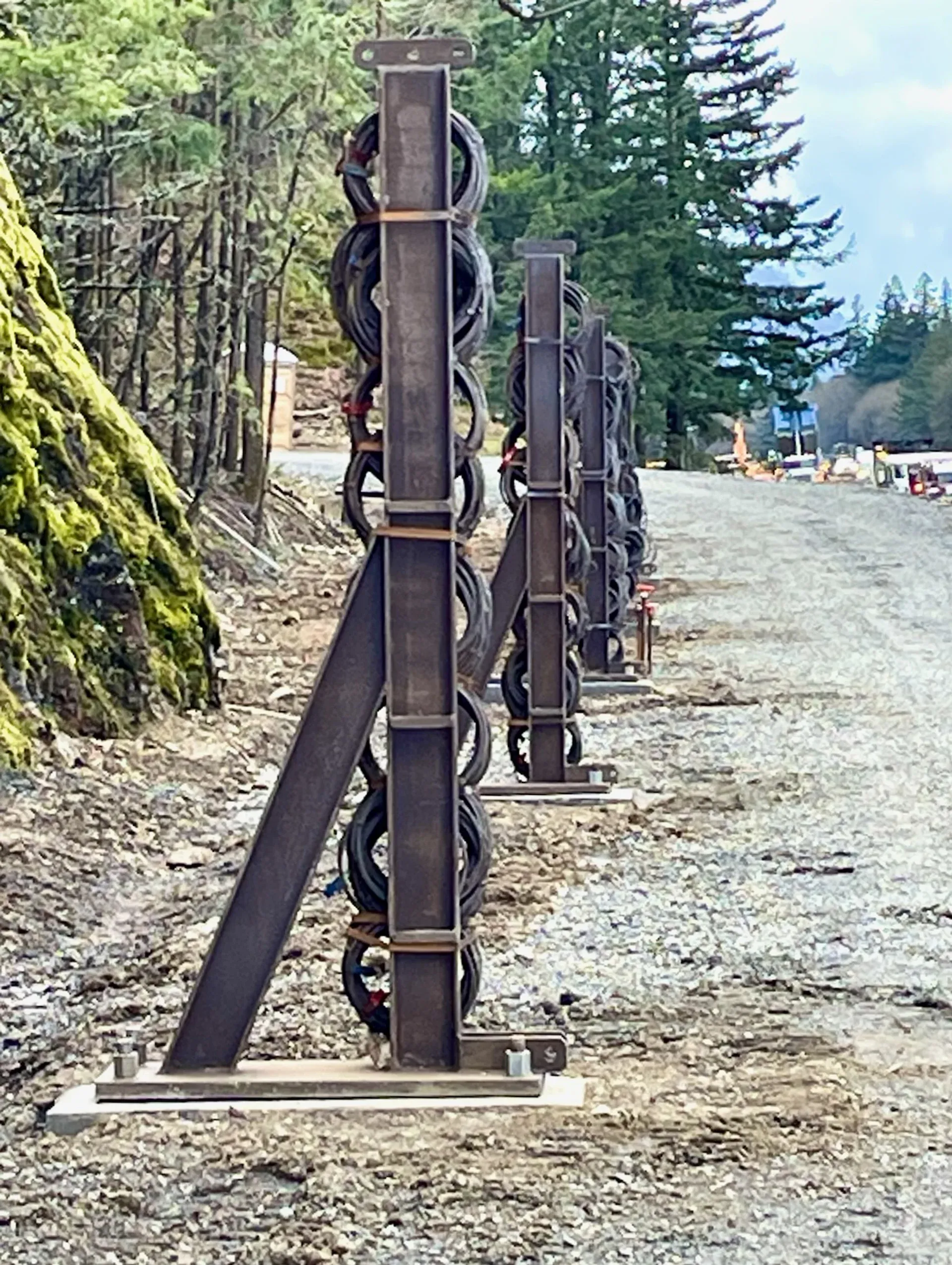
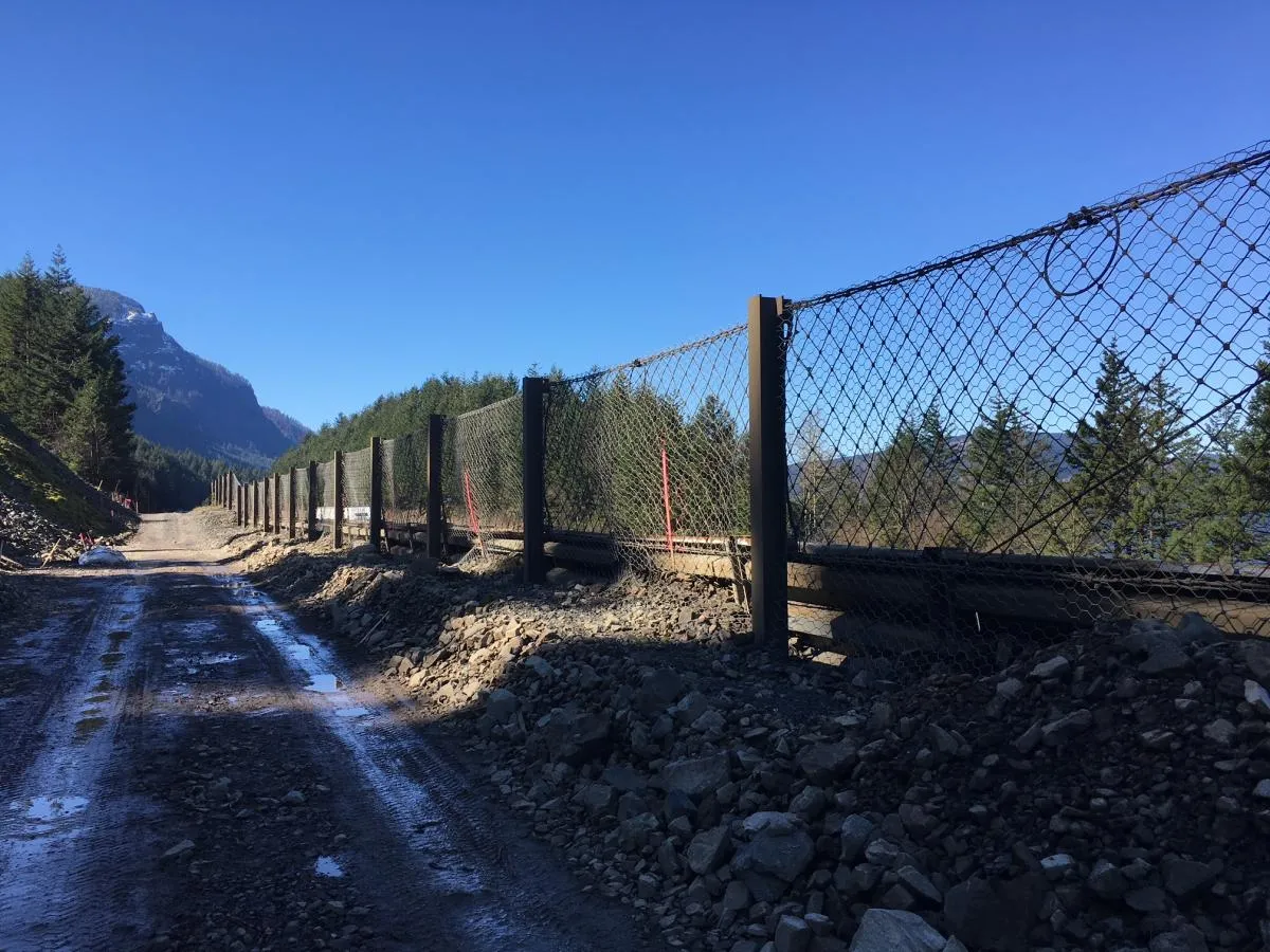
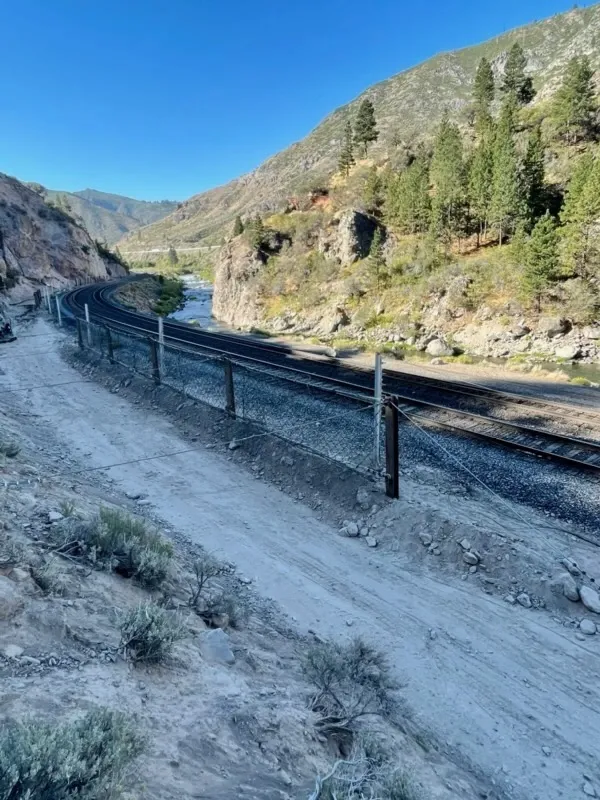
Post Erection
Heavy hinged steel posts (W-section or built-up) mounted on shear-pin or articulated base plates per kit specification. Post sections and base plates are sized up from standard barrier components.
4
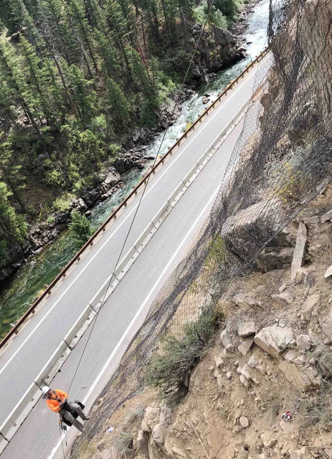
Cable and Brake Element Installation
Upslope and lateral support cables tensioned to ground anchors, brake elements with 2 to 3+ meter stroke installed in line and pre-loaded per certification.
5
Ring Net Installation
Class 7-8 ring net (300 to 350 mm rings, 3 to 4 mm wire) mounted across the post array, panels seamed and tensioned per kit certification.