Tieback Anchors

Tieback Anchors

Tieback anchors are post-tensioned ground anchors that drill through a wall facing into competent soil or rock, develop bond along a deep fixed length, and are stressed to lock in 100 to 600 plus kips of holding load. They provide the active lateral restraint behind soldier pile walls, secant pile walls, foundation tie-ins, and dam abutments where passive systems would not develop adequate capacity.

100-600+
Kips per Anchor
25-200+
Ft Tendon Length
133%
Proof Test Load
75+
Year Design Life
Overview

Understanding Tieback Anchors

Tieback anchors are the active lateral restraint system specified for excavation shoring, retaining wall reinforcement, foundation tie-ins, and dam-abutment retention when load demand exceeds the capacity of passive elements. A drilled-and-grouted anchor is post-tensioned at install against a wall facing or bearing plate, locking in 100 to 600 plus kips of holding load before the wall begins to deflect. The anchor pairs routinely with soldier pile walls, secant pile walls, and H-pile walls for deep urban excavations, with structural shotcrete facings on cut slopes, and with micropile foundations where lateral and vertical demand are both present. On hybrid walls, the upper rows often use tiebacks where loads concentrate and the lower rows transition to soil nails through the rest of the face.

What Are Tieback Anchors?

A tieback anchor is a post-tensioned ground anchor consisting of a steel tendon, either a bundle of seven-wire prestressing strands or a high-strength threadbar, drilled through a wall facing or excavation face into stable ground beyond the active failure surface, grouted along a defined bonded fixed length, and post-tensioned against a bearing plate using a hydraulic stressing jack. The unbonded free length passes through the active wedge without engaging the failing soil, so the entire tendon force transfers from the wall facing through the free length into the bonded fixed length seated deep in competent ground. The terms tieback anchor, ground anchor, and prestressed anchor are used interchangeably across the industry, with the FHWA Geotechnical Engineering Circular No. 4 (FHWA-IF-99-015) and PTI DC35.1 as the canonical design references.

Tiebacks differ from passive ground reinforcement in two respects. First, they carry preload at install, meaning they apply lateral restraint from day one rather than waiting for the wall or slope to deform before developing tension. Second, individual anchor capacities are an order of magnitude higher than passive elements: a single multi-strand tieback typically carries 100 to 600 plus kips, where a soil nail develops 15 to 60 kips. Modern civil practice traces back to the 1958 Bauer prestressed soil anchor in Munich, with the system entering FHWA and AASHTO design practice in the 1970s for highway retaining walls and bridge abutments. Permanent installations require double corrosion protection (PTI Class I encapsulation) and design service lives of 75 to 100 plus years.

Key Benefits

  • High load capacity in compact package
  • Active pre-loaded system
  • Allows deeper excavations
  • Reduces wall thickness requirements
  • Long-term corrosion protection available
The Engineering

How Tieback Anchors Work

How the system carries load in service, and how we build it on site.

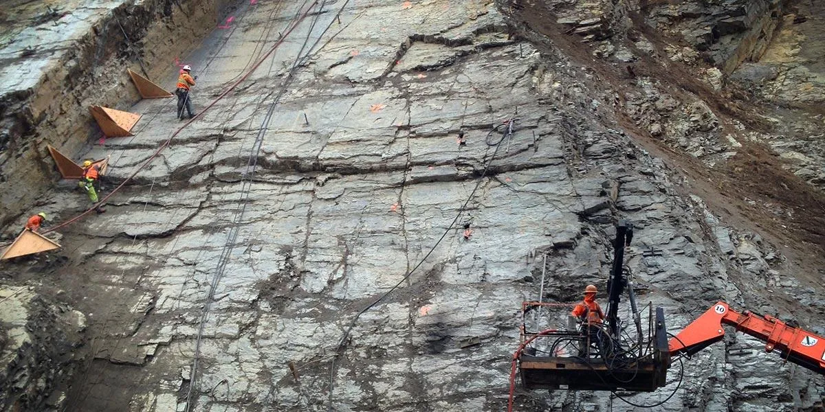
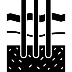
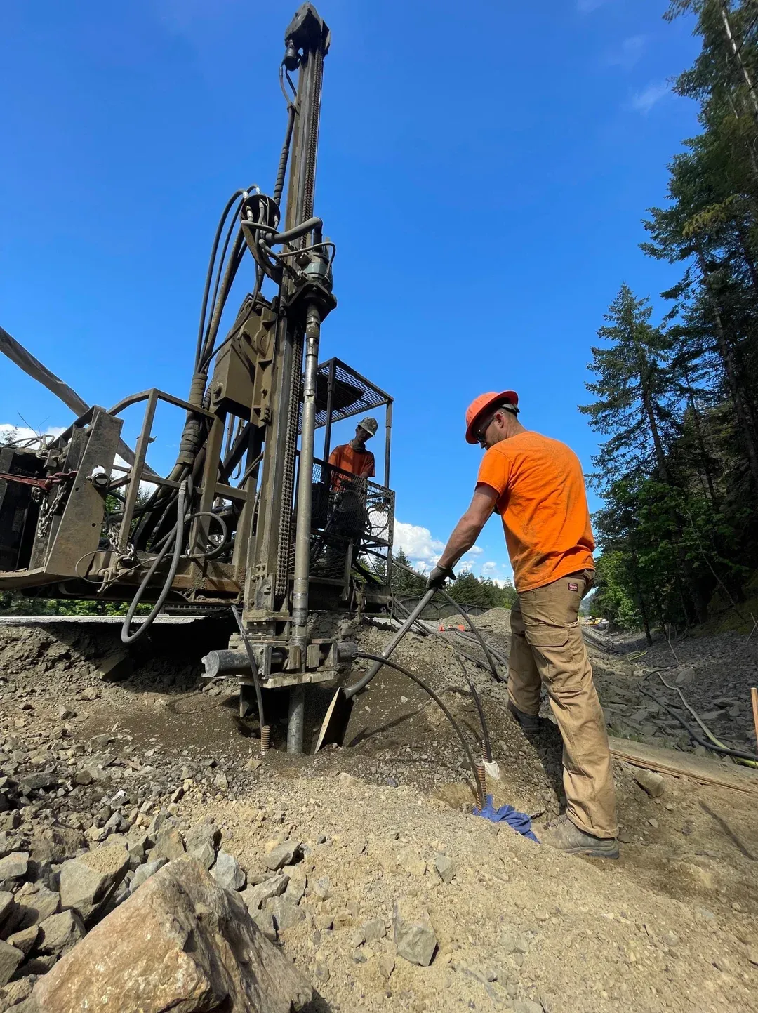
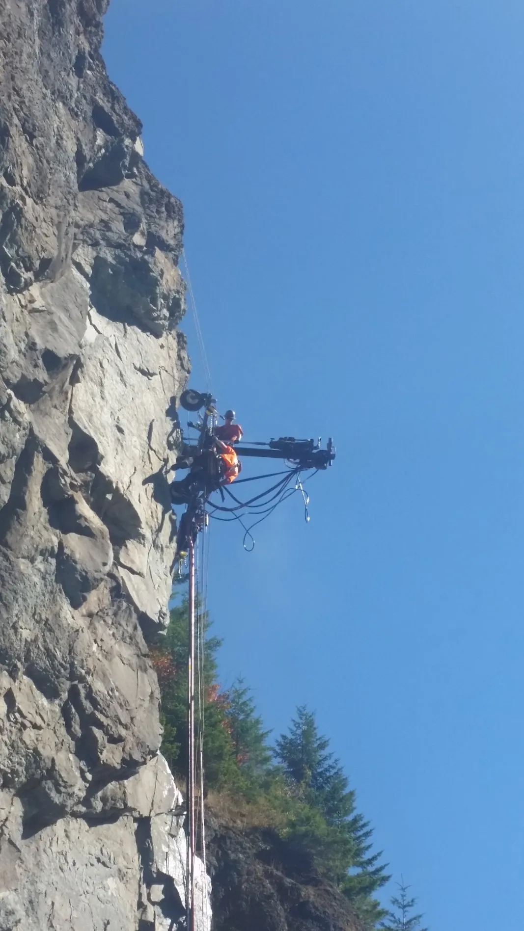
Construction begins with rotary or rotary-percussion drilling of an anchor borehole through the wall facing, soldier pile flange, or excavation face, advanced at a downward inclination of 15 to 30 degrees beyond the active failure surface and into competent soil or rock. Borehole diameter is typically 4 to 8 inches, sized to accommodate the tendon, the encapsulation sheath in permanent applications, and the required grout cover. Hollow-stem augers, duplex drills, or temporary casing systems are used in caving ground to keep the hole open until the tendon is in place.

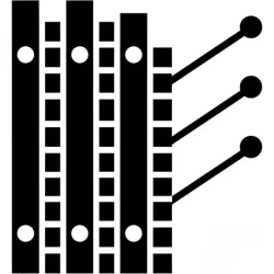
The tendon, either a bundle of 0.5 or 0.6 inch seven-wire strands meeting ASTM A416 (Grade 270) or a single high-strength threadbar meeting ASTM A722 (Grade 75 to Grade 150), is fabricated to project length with the unbonded free length sleeved in a smooth plastic sheath filled with corrosion-inhibiting grease and the bonded fixed length left bare or encapsulated in a corrugated plastic duct depending on the corrosion class. The assembly is inserted with centralizers to maintain consistent grout cover, and neat cement grout is pumped through a tremie line from the toe upward, displacing drilling fluid and filling the bonded length. Pressure grouting is sometimes used along the fixed length to improve bond capacity in granular soils.

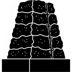
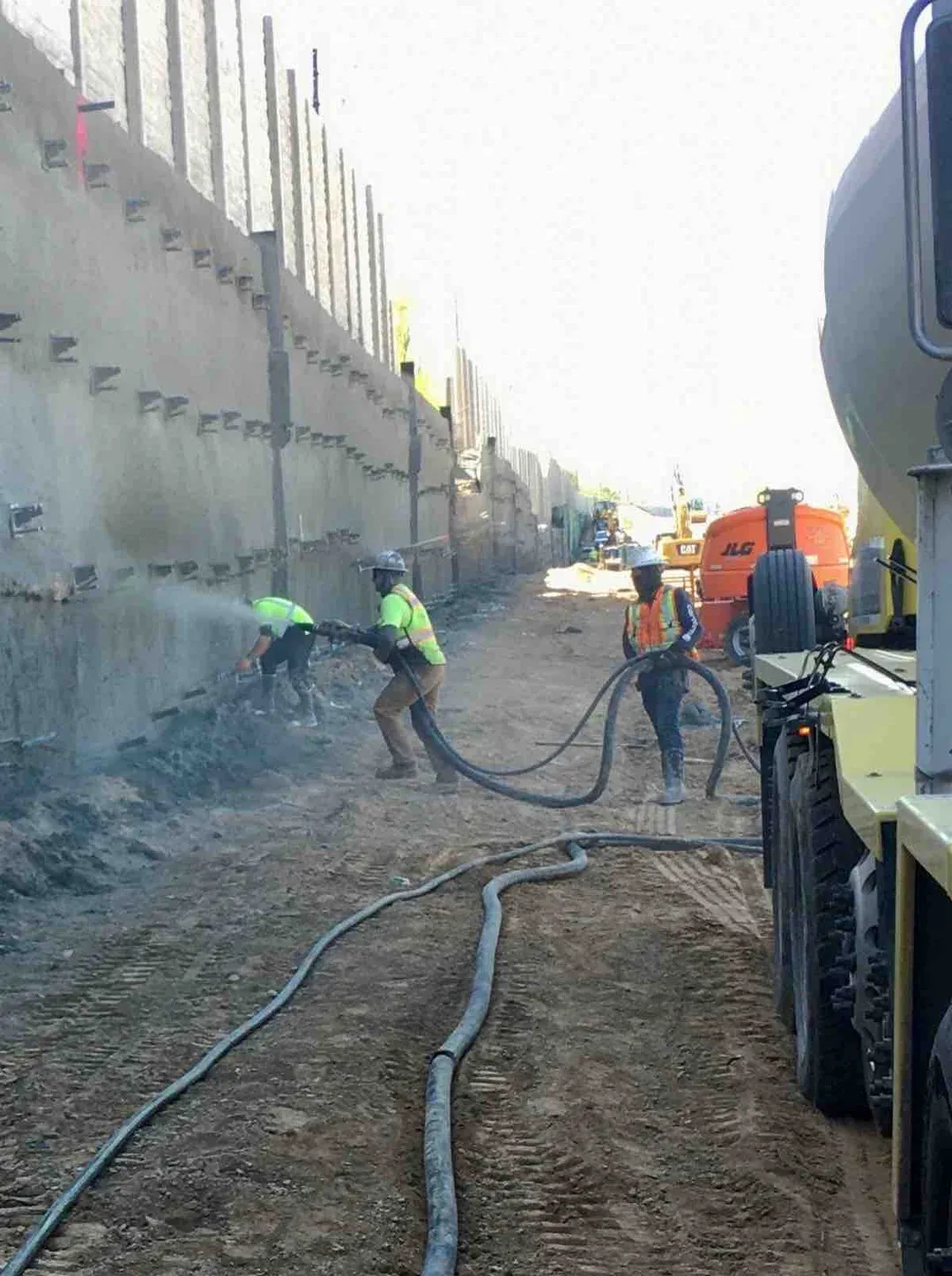
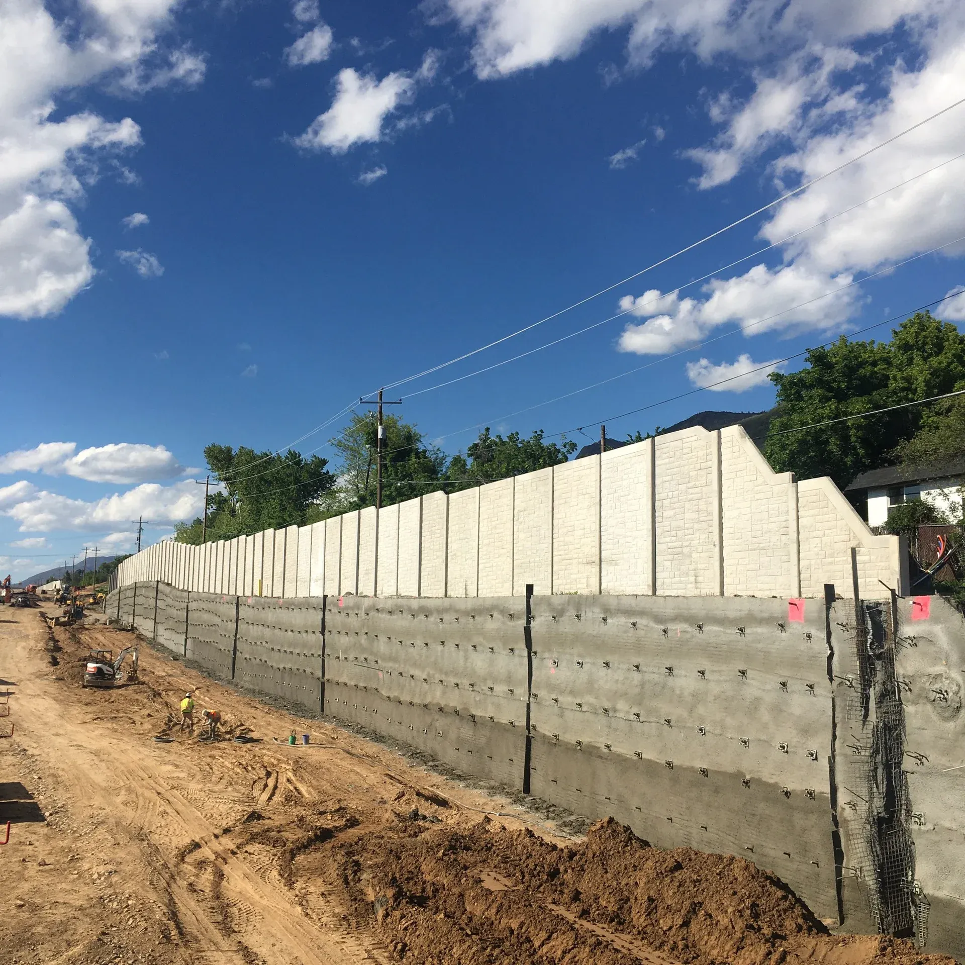
Once grout has reached design strength, typically 7 to 10 days for cement, the anchor is stressed against a steel bearing plate seated against the wall facing using a hydraulic multi-strand or monobar jack. The tendon is loaded through a defined performance test or proof test sequence, with displacement measured at each load increment to verify capacity, identify creep behavior, and confirm that the bonded fixed length is fully engaged. After stressing, the load is transferred to the structure by setting wedges (strand) or running a nut down the threaded end (bar), locking in the design load. Permanent anchors are then sealed with a grouted anchor head and protective cover. Every production anchor is proof-tested to typically 133 percent of design load, and selected anchors receive performance and creep tests per PTI DC35.1 acceptance criteria.

1

Drilling

Drill through wall or slope face into stable bearing zone at designed angle and depth.

2

Tendon Installation

Insert strand bundle or threadbar with centralizers and corrosion protection.

3

Grouting

Pressure grout the bond zone to develop anchor capacity in surrounding ground.

4

Stressing & Lock-Off

Tension anchor to design load, verify performance, and lock off at bearing plate.

System Variants

Types of Tieback Anchors

Type 01

Strand Tendon Anchors

Strand tendon anchors use a bundle of 0.5 or 0.6 inch diameter seven-wire prestressing strands meeting ASTM A416 Grade 270, with the bundle scaling from 4 to 12 or more strands depending on design load. They are the high-capacity workhorse of the industry, routinely sized between 200 and 600 plus kips per anchor and used on the deepest urban excavations, the tallest soldier pile walls, dam abutments, and bridge retaining walls where load demand exceeds what a single threadbar can carry. Long free lengths are practical because strand bundles coil for shipping and handling, so 80 to 150 plus foot anchors are routine. Stressing requires a multi-strand hydraulic jack, and load transfer at the head is by individual wedges seated into a tapered anchor block.

Type 02

Bar (Threadbar) Anchors

Bar anchors use a single high-strength continuously threaded steel bar meeting ASTM A722 in Grade 75, 95, 100, or 150, typically 1 inch to 1-3/4 inch diameter. They are simpler to fabricate, install, and stress than strand systems, with the head transfer by a calibrated nut run down the threaded bar against a bearing plate. Capacities range from approximately 50 kips for the smallest Grade 75 bars up to 350 kips for large-diameter Grade 150, which covers the vast majority of moderate-load shoring, foundation tie-in, and slope stabilization applications. Bars also have the advantage of being restressable, since the nut can be re-torqued at any time during the service life if monitoring indicates load loss. Maximum practical free length is shorter than strand because long bars require splice couplers, but on most excavation projects bar anchors and strand anchors are interchangeable below the 350 kip threshold.

Type 03

Removable Tendon Anchors

Removable anchors are designed for extraction at end-of-service, leaving no permanent encroachment on neighboring property. The tendon is engineered with a release mechanism, typically a center-pull strand de-stranding system or a frangible coupling, that allows the strands or bar to be pulled back through the bond zone after the temporary excavation is complete and the permanent structure has been backfilled. They are the system of choice on tight urban sites where the active anchor zone would otherwise extend under adjacent property without an easement, since recoverable systems eliminate the long-term encroachment that would block future development. Capacities are comparable to standard temporary strand or bar anchors. The tradeoff is materials cost: removable systems carry a meaningful premium per anchor over conventional temporary anchors, justified only when easement acquisition is impractical or impossible.

Side By Side

Tieback Anchors vs Other Reinforcement Systems

VS

Tieback Anchor vs Soil Nail

The defining difference is active versus passive load and the resulting capacity scale. A tieback anchor is post-tensioned at install, locking in 100 to 600 plus kips of holding load before the wall deflects, with an unbonded free length passing through the active wedge and a bonded fixed length seated deep in stable ground. A soil nail carries no preload and develops 15 to 60 kips of tension only as the soil tries to move outward, with the bar bonded continuously along its full length. Geometry differs accordingly: tiebacks have a defined free-length and fixed-length split, while soil nails are fully grouted end to end. Selection follows the load demand. When a wall is taller than approximately 25 feet or carries surcharge from adjacent structures, tieback anchors are the right tool. When the cut is moderate height and the soil mass behaves as a coherent reinforced volume, soil nailing is materially less expensive. Tall hybrid walls combine the two, with tiebacks at the upper portion and soil nails through the lower face.

VS

Tieback Anchor vs Rock Bolt

The defining difference is depth, capacity, and whether the bar resists direct tension or transfers it to a wall facing. A tieback anchor is long (25 to 200 plus feet), has an unbonded free length plus a bonded fixed length seated deep in stable rock or soil, and is post-tensioned against a soldier pile, secant pile, or wall facing to apply 100 to 600 plus kips of holding force. A rock bolt is short (4 to 25 feet), grouted along most or all of its length, and ties surface blocks back to competent rock immediately behind the failure zone. Tieback anchors work as the lateral restraint for excavation shoring walls and dam-abutment retention; rock bolts work as the primary internal support in tunnels and on rock cuts. Both can appear on the same project, with rock bolts handling near-surface block stability and tieback anchors carrying the deep retaining load.

VS

Tieback Anchor vs Deadman Anchor

Both systems resist lateral wall load by transferring tendon force into ground beyond the active failure surface, but the load-transfer mechanism is fundamentally different. A tieback anchor develops capacity through grout-to-ground bond along a drilled-and-grouted bonded fixed length seated deep in competent material, requires only the borehole diameter at the wall face, and can be installed with the wall already in place. A deadman anchor relies on the passive earth pressure mobilized against a buried mass, either a concrete block, a sheet-pile cell, or a pile group, connected back to the wall through a tie rod. Deadmen require open-cut excavation behind the wall to install the buried mass, take significant lateral footprint, and are practical only on greenfield waterfront and bulkhead work where backland is open. On urban excavations, dam abutment retention, and any project where the wall is built top-down or where adjacent property prevents open-cut behind the alignment, drilled-and-grouted tiebacks are the only viable option.

Not sure which system fits? We'll walk through the tradeoffs for your site conditions.

Talk Through Your Options
Where It Fits

Common Applications and Project Types

Deep urban excavations are the largest single market for tieback anchors, with multi-tier anchor systems supporting soldier pile, secant pile, and slurry walls down to basement subgrades 40 to 80 plus feet below street level. Highway and railway cut slopes follow, where AASHTO LRFD §11.9 anchored wall design governs the use of tiebacks on permanent retaining structures along transportation corridors through hillsides and against bridge abutments. Dam, spillway, and lock structure anchoring under USACE and Bureau of Reclamation programs uses high-capacity post-tensioned anchors to hold concrete monoliths and rock blocks against uplift and overturning loads, with the dam-monolith tie-down typically using multi-strand cable anchors sized to the 1000 to 2000 plus kip range, often combined with structural shotcrete facings on the abutment rock cuts. Foundation underpinning of existing structures uses tiebacks to restrain bowing basement walls, anchor down spread footings under uplift, and tie historic foundations to bedrock for seismic retrofit. Slope stabilization in active landslide zones deploys high-capacity anchors that transfer building or roadway loads through the failure surface to stable ground below.

Retaining wall lateral support
Deep excavation shoring
Slope stabilization
Dam and spillway anchoring
Bridge abutment reinforcement
Existing wall remediation
Benefits

Key Advantages

Active Load Resistance

Unlike passive systems, tiebacks are pre-stressed to design load, immediately resisting lateral forces without requiring wall movement.

High Capacity

Multi-strand anchors develop capacities exceeding 500 kips, supporting deep excavations and heavy structures.

Proof Testing

Every anchor is tested to verify capacity before lock-off, ensuring reliable performance.

Design Flexibility

Anchors can be installed at various angles and lengths to optimize load transfer into available bearing material.

Long Service Life

Double corrosion protection (PTI Class I) provides 75 to 100 plus year service life for permanent installations.

Engineering

Technical Considerations

Soil/Rock Conditions

Bond zone must be in competent material. Rock provides highest capacity; soil anchors require longer bond lengths. Casing may be needed in caving ground.

Groundwater

Grouting methods adapted for wet conditions. Corrosion protection essential in aggressive groundwater environments.

Load Capacity

Capacity depends on tendon size, grout strength, and bond length in bearing material. All anchors proof-tested to 133% of design load per PTI DC35.1.

Spacing

Anchor spacing determined by wall design and allowable loads. Typical spacing 6-10 ft horizontal, one or more rows vertically.

Installation Method

Rotary or percussion drilling at design angle. Tendon placed with centralizers, grouted under pressure, stressed after grout cure.

Equipment Used

  • Track or crane-mounted drill rigs
  • Hollow-stem augers or casing systems
  • Grout mixing and pumping equipment
  • Multi-strand stressing jacks
  • Load cells and pressure gauges

Limitations

  • Requires access beyond property line or easements
  • Bond zone must be in stable material
  • Corrosion protection critical for permanent anchors
  • Creep testing required for some soil conditions

Technical Specifications

Anchor Type
Strand / Threadbar
Capacity
50 to 600+ kips
Bond Length
15 ft to 50 ft
Corrosion Protection
PTI Class I / Class II
Codes And References

Engineering Standards and References

PTI

DC35.1

Recommendations for Prestressed Rock and Soil Anchors

The canonical industry-consensus design and acceptance reference for ground anchors in North America. Defines corrosion-protection classes (Class I encapsulated, Class II grout-protected), tendon materials, free-length and fixed-length geometry, and proof / performance / creep test acceptance criteria.

FHWA

FHWA-IF-99-015

Geotechnical Engineering Circular No. 4: Ground Anchors and Anchored Systems

Sabatini, Pass, and Bachus 1999. The FHWA design manual for ground anchors and anchored walls on federal highway projects. Covers anchor selection, bond-length design in soil and rock, corrosion protection, and acceptance testing.

AASHTO

LRFD §11.9

Anchored Walls

Section 11.9 of the AASHTO LRFD Bridge Design Specifications governs anchored retaining walls on state DOT bridge and highway projects, including load and resistance factors, design checks, and corrosion-protection requirements for permanent installations.

Gallery

Our Work in Action

Expertise

Why Choose Rock Supremacy for Tieback Anchors

PTI-Trained Crews

Our installers are trained in Post-Tensioning Institute procedures for ground anchor installation, stressing, and acceptance testing.

Full Testing Capability

In-house multi-strand and monobar stressing jacks, calibrated load cells, and experienced technicians for proof, performance, and creep testing per PTI DC35.1.

Difficult Access Expertise

Track-mounted and limited-access rigs allow tieback installation in constrained urban and mountainous sites.

Quality Documentation

Complete installation records including drilling logs, grout takes, and test results for owner files.

Integrated Solutions

We combine tiebacks with soldier piles, shotcrete, and drainage for complete excavation support systems.

Questions

Tieback Anchors FAQ

A tieback anchor is a post-tensioned ground anchor consisting of a steel tendon, either a bundle of seven-wire strands or a high-strength threadbar, drilled through a wall facing into stable ground beyond the active failure surface, grouted along a bonded fixed length, and stressed against a bearing plate. The unbonded free length passes through the active wedge without engaging the failing soil, transferring full load into the bonded fixed length seated deep in competent material. Tiebacks are the standard active lateral restraint for deep excavations, retaining walls, dam abutments, and foundation tie-ins.
Single threadbar anchors typically carry 50 to 350 kips. Multi-strand anchors routinely carry 200 to 600 plus kips per anchor. Capacity is governed by tendon size and grade (ASTM A416 strand or ASTM A722 bar), bond length, and the strength and stiffness of the ground in the bonded fixed length. Every production anchor is proof-tested to 133 percent of design load per PTI DC35.1 acceptance criteria, and selected anchors receive performance and creep tests to verify long-term load retention.
Tieback anchors are post-tensioned at install and develop 100 to 600 plus kips of holding load through a deep bonded fixed length, with an unbonded free length passing through the active wedge. Soil nails are passive, fully grouted along their full length, and develop 15 to 60 kips of tension only after the soil tries to move outward. Tiebacks are the right tool when wall load demand is high or surcharge is concentrated; soil nailing is materially less expensive on moderate-height cuts. Tall hybrid walls often use tiebacks at the upper portion and soil nails through the lower face.
After drilling and tendon insertion, neat cement grout is pumped through a tremie line from the toe of the bond zone upward, displacing drilling fluid and filling the bonded length around the tendon. Pressure grouting is sometimes used to improve bond capacity in granular soils. Once grout reaches design strength, typically 7 to 10 days, the anchor is stressed against a steel bearing plate using a hydraulic multi-strand or monobar jack. The tendon is loaded incrementally with displacement readings at each step, and after stressing, load transfer is locked in by setting wedges (strand) or torquing a nut (bar).
Temporary anchors are designed for the duration of construction, typically 18 to 24 months. Permanent anchors with PTI Class I encapsulation (double corrosion protection) are designed for service lives of 75 to 100 plus years and are routinely specified on highway, railway, dam, and bridge structures. Service life depends on corrosion-protection class, ground aggressivity, grout cover, and quality of installation. AASHTO LRFD §11.9 and PTI DC35.1 govern permanent anchor design on transportation projects.
PTI DC35.1, Recommendations for Prestressed Rock and Soil Anchors, is the canonical North American consensus document for tendon materials, corrosion classes, and acceptance testing. FHWA Geotechnical Engineering Circular No. 4 (FHWA-IF-99-015, Sabatini Pass and Bachus 1999) is the FHWA design manual for ground anchors and anchored walls. AASHTO LRFD Bridge Design Specifications §11.9 governs anchored walls on state DOT bridge and highway projects. Tendon materials follow ASTM A416 (strand) and ASTM A722 (threadbar).
Yes. Every production anchor is proof-tested to 133 percent of design load per PTI DC35.1 before lock-off. A subset of anchors receives performance tests with cyclic loading and unloading to verify load-extension behavior across the full design range, and creep tests with extended load-hold periods to confirm long-term capacity in cohesive soils. Tests are conducted with calibrated multi-strand or monobar jacks and load cells, with displacement and load recorded at each increment.
Permanent tieback anchors that extend beyond property lines into adjacent ground require a permanent subsurface easement from the affected property owner, typically negotiated as part of the project scope. Removable tendon anchors are designed to be extracted at end-of-construction, leaving no permanent encroachment, and are the system of choice on tight urban sites where easement acquisition is impractical. The tradeoff is materials cost: removable systems carry a meaningful premium per anchor over conventional temporary anchors.
Tiebacks require a competent bond zone capable of developing the design tendon load through grout-to-ground bond. Rock and dense soils provide the highest bond capacity; medium-dense to stiff soils require longer bond lengths and sometimes pressure grouting; very soft clays or organic soils may not develop adequate bond and require alternative systems such as deadman anchors, sheet-pile cofferdams, or wider-base gravity walls. Site-specific bond capacity is verified by performance tests on sacrificial pre-production anchors before full-scale installation begins.
Testimonials

Client Testimonials

Trusted by DOTs, engineering firms, and property owners nationwide.

Contact

Deploy Us

Ready to discuss your project? Our team is standing by to assess your site conditions and develop a custom solution using Tieback Anchors and other proven techniques.

Emergency (24/7)

(541) 383-7625

Bidding & Estimates

Info@RockSupremacy.com

Headquarters

Western Division (HQ)
65147 N Hwy 97
Bend, OR 97701
Eastern Division
915 Millennium Ct
Blountville, TN 37617

Licensed in CO, UT, WY, ID, MT, CA, WA, OR, TN, VA

Request Consultation