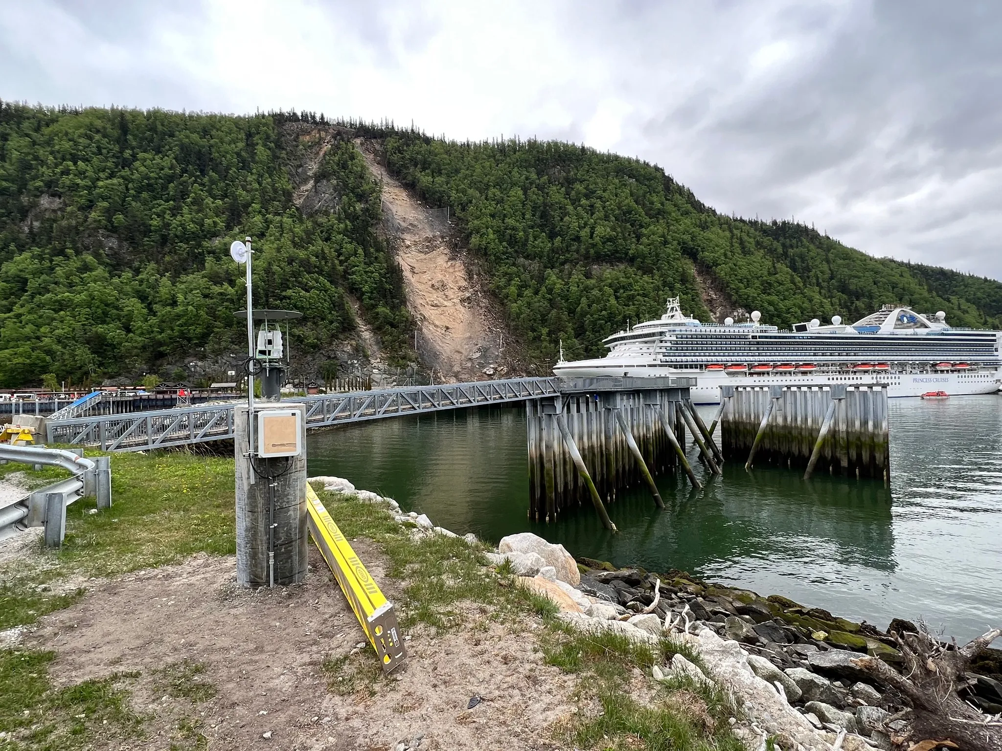
Design begins with rockfall trajectory simulation, typically Colorado Rockfall Simulation Program (CRSP), RocFall, or RAMMS::Rockfall, which uses block size, source location, slope geometry, and surface restitution coefficients to predict bounce heights, velocities, and kinetic energies along the slope. The candidate attenuator line is placed where the predicted bounce height clears the panel envelope and the predicted energy stays within the system's certified Maximum Energy Level. Practical placement falls in the 30 to 50 percent of slope-height band, high enough to engage rocks before they reach toe-velocity but low enough to capture the bulk of the upper source area within the panel's coverage.
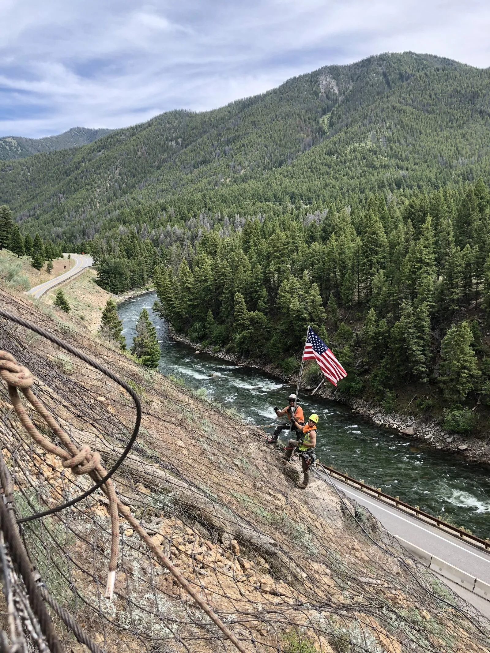
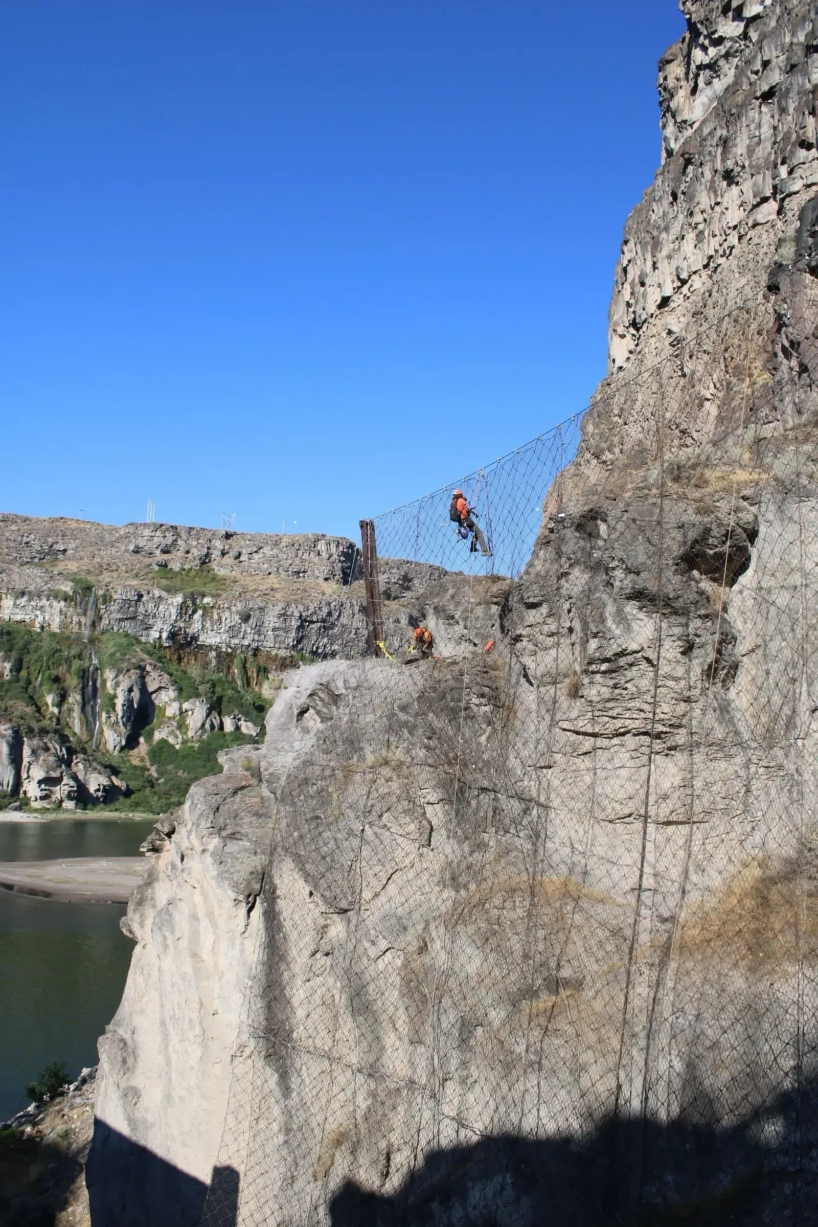
Top anchors are drilled and grouted along the upper attachment line, typically rock bolts or prestressed cable anchors at 10 to 20 ft spacing depending on rock quality and design load. Wire-rope or ring-net panels hang from the support cables with brake elements integrated into the upslope and lateral cable terminations. When a block engages the panel the net deflects through 0.5 to 2 m of stroke, the deflection pulls tension into the support cables, and the brake elements extend through controlled friction or ring deformation, converting kinetic energy into inelastic work rather than reflecting it as elastic rebound off a rigid surface. On a suspended attenuator the decelerated block exits the open bottom edge moving at a fraction of its pre-engagement velocity and drops into a downstream catchment ditch, gabion berm, or smaller-class toe barrier sized for the reduced energy. On an anchored attenuator the bottom restraint contains the block at mid-slope and the system functions as a flexible barrier installed on the slope rather than at its base.
1
Rockfall Trajectory Analysis
Model rockfall paths using 2D or 3D simulation software to identify optimal interception points. Analysis determines rock velocities, bounce heights, and energy levels at various slope positions to size the attenuator system appropriately.
2
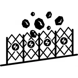
Anchor System Design
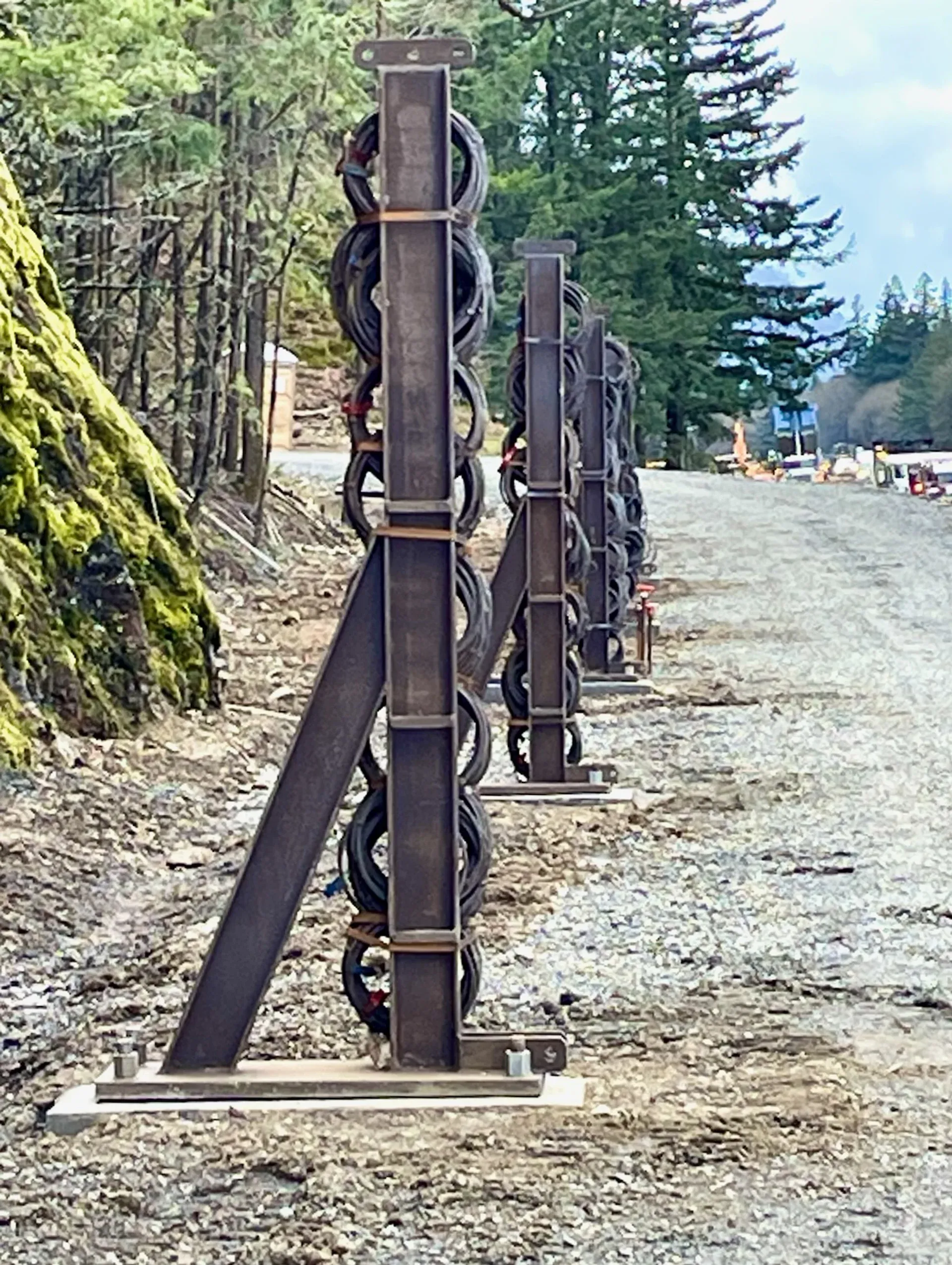
Design anchor patterns for top support, intermediate suspension points, and lateral restraint. Anchors must resist both static mesh weight and dynamic impact loads during rockfall events.
3
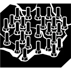
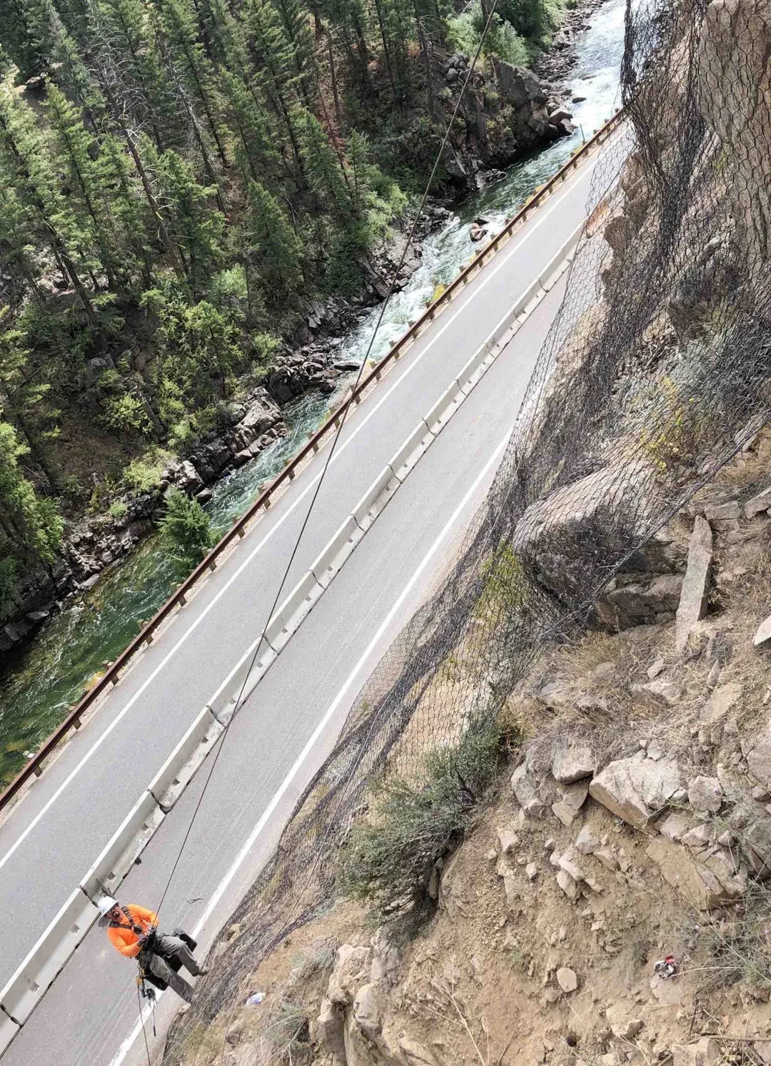
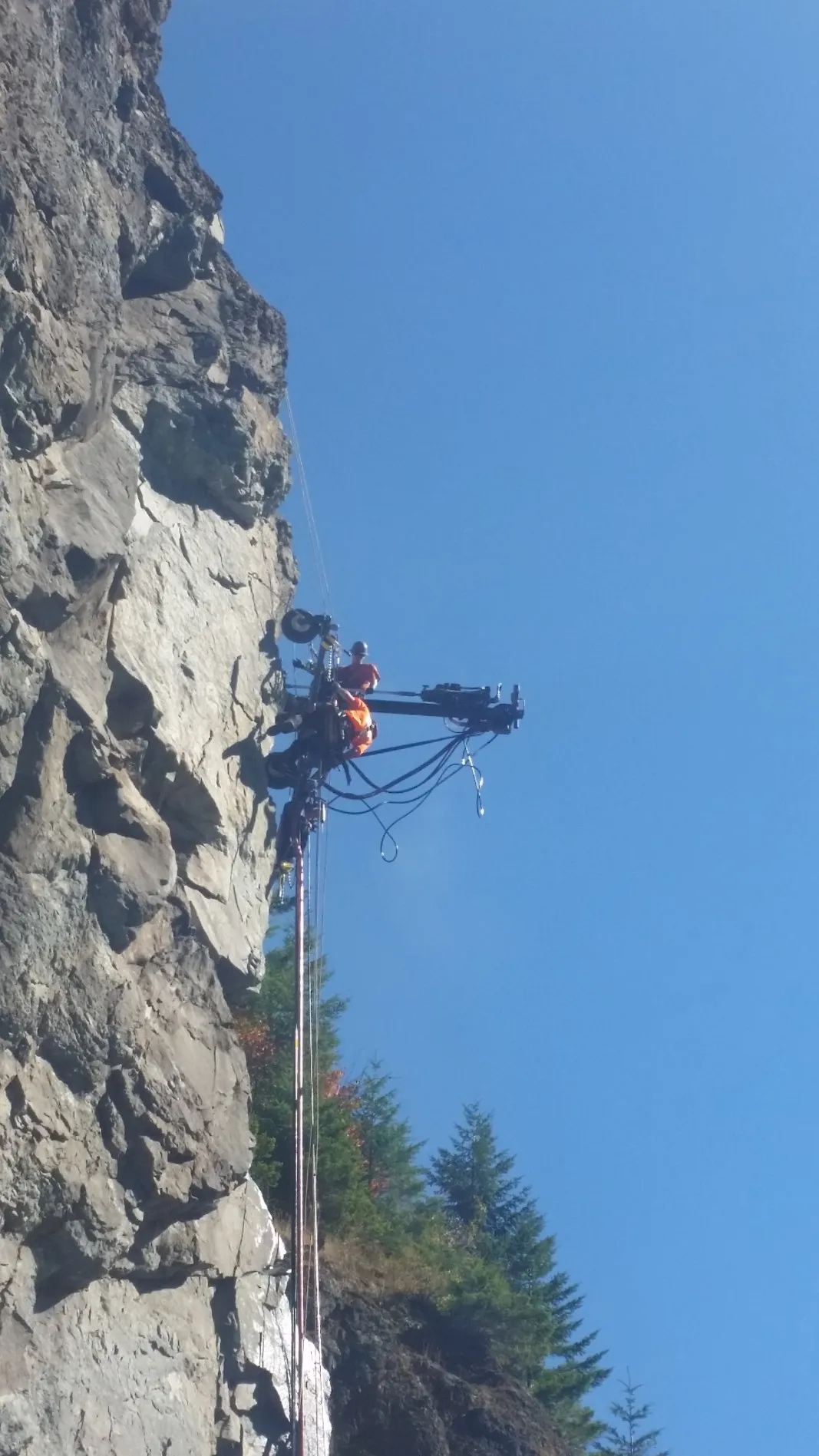
Top Anchor Installation
Install rock bolts or cable anchors at the top attachment line using rope access or mechanical drilling. Anchors are load-tested to verify capacity before mesh attachment.
4
Mesh Panel Deployment
Deploy wire rope nets or ring net panels from top anchors, incorporating energy-absorbing brake elements at connection points. Panels are joined with shackles or ferrules to create continuous coverage.
5
Energy Absorber Installation
Install compression brakes, friction brakes, or ring-net deformation elements that absorb impact energy by controlled deformation. These elements are the key to attenuator performance.
6
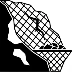
Base Termination
Terminate the bottom edge with ground anchors for full containment, or allow controlled release toward a lower catchment system. Termination method depends on overall rockfall management strategy.