Weep Drains

Weep Drains

Weep drains are short through-facing drainage outlets that discharge water trapped behind retaining walls, MSE walls, soldier pile walls, and shotcrete-faced soil nail walls before hydrostatic pressure can drive facing detachment, wall tilt, or freeze-thaw damage. Standard detail per AASHTO LRFD §11.10.8.

5-10 ft
Grid Spacing
2-4 in
PVC Drain
75+ Yr
Design Life
Passive
Gravity Flow
Overview

Understanding Weep Drains

Weep drains are the through-facing relief outlets that protect retaining walls from hydrostatic pressure, the leading cause of retaining wall failure. Water that migrates behind MSE walls, soldier pile walls, structural shotcrete facings, and shotcrete-faced soil nail walls is collected by chimney and blanket drains, then discharged through 2 to 4 inch PVC weep pipes daylighted on a 5 to 10 ft grid, holding the back-of-wall pore pressure at or near zero.

The detail is small but mandatory. AASHTO LRFD §11.10.8, FHWA-NHI-10-024 for MSE walls, and FHWA GEC-7 for shotcrete-faced soil nail walls all specify weep drainage as a design requirement, not an option. On landslide and slope stabilization sites, weeps pair with horizontal drains, the horizontal drains lower the regional groundwater table within the slope mass, and the weeps clear any residual seepage at the new facing for a fully dewatered wall.

What Is a Weep Drain?

A weep drain is a short, through-facing drainage outlet that discharges water trapped behind a wall or shotcrete face before hydrostatic pressure can build. The classic detail is a 2 to 4 inch schedule 40 PVC pipe set through the facing with an AASHTO M 288 Class 2 nonwoven geotextile filter sock (or a graded gravel pack per AASHTO M 43) on the back end, sloped at 2 to 5 percent downward so collected seepage drains by gravity. The terms weep drain, weep hole, and through-wall drain are used interchangeably across the geotechnical and structural literature.

Weep drains appear on virtually every permanent retaining wall, MSE wall, soldier pile wall, and shotcrete-faced soil nail wall in the geotechnical canon, and AASHTO LRFD §11.10.8 makes wall drainage a design requirement, not an option. The role is narrow but critical, hydrostatic pressure is the leading cause of retaining wall failure. A weep drain does not collect groundwater the way a horizontal drain does, it relieves whatever water has already reached the back of the facing, preventing the buildup that drives wall tilt, shotcrete debonding, and freeze-thaw spalling.

Key Benefits

  • Standard detail on permanent retaining walls per AASHTO LRFD §11.10.8
  • Relieves the hydrostatic pressure that causes most retaining wall failures
  • Prevents shotcrete debonding, facing detachment, and freeze-thaw spalling
  • Passive gravity operation with no pumps, power, or moving parts
  • Visible discharge confirms drainage system performance
The Engineering

How a Weep Drain Works

How the system carries load in service, and how we build it on site.

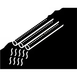
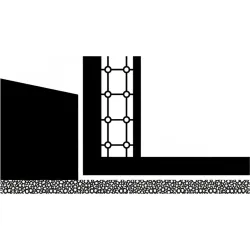
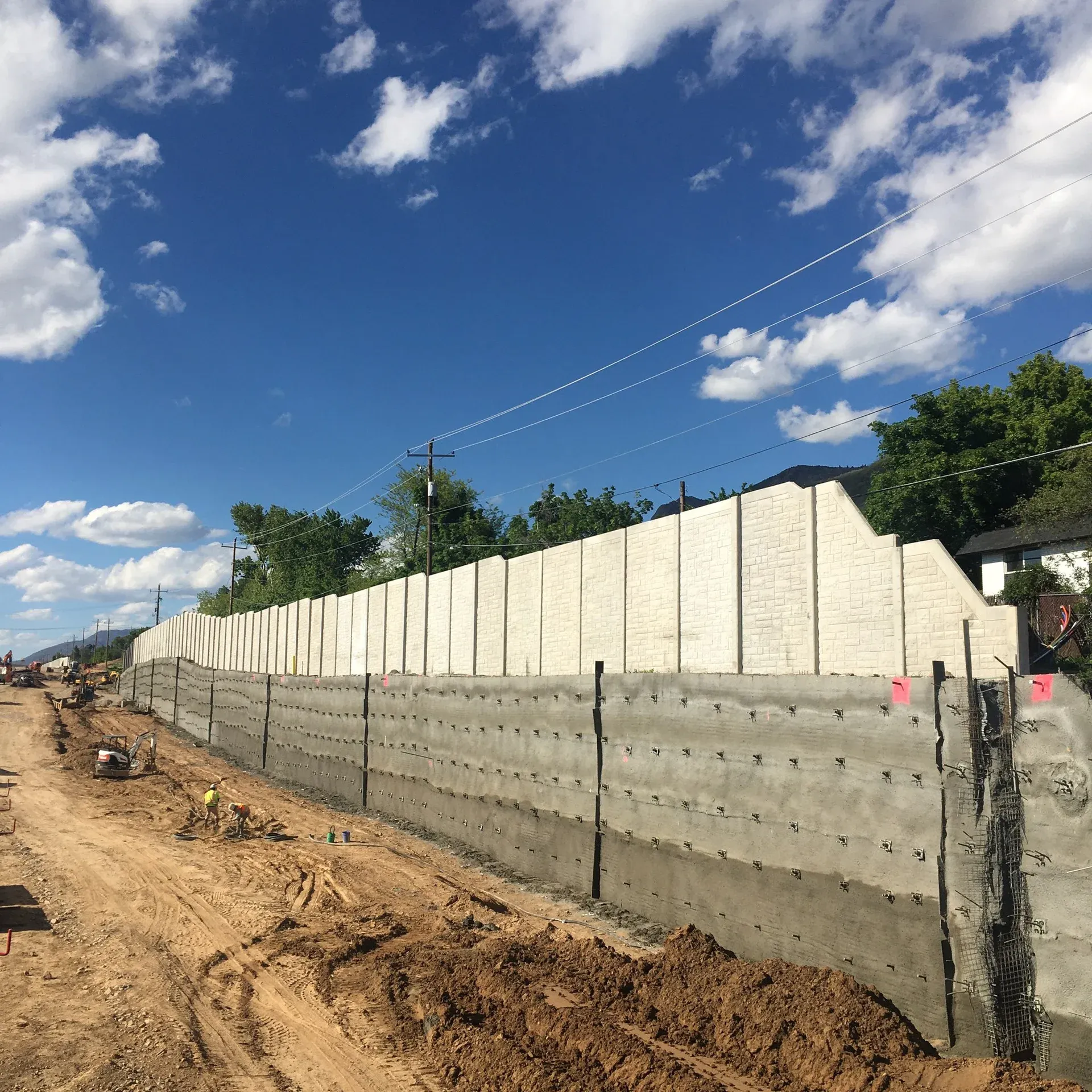
Behind a wall facing, water moves under gravity through soil pores or, on engineered walls, through a chimney drain of clean open-graded aggregate placed against the back of the facing. When that water reaches the weep drain inlet, a geotextile sock or graded gravel pack screens out fines, and the water enters a 2 to 4 inch PVC pipe that pierces the facing. The pipe is set with a positive downward gradient, typically 2 to 5 percent toward daylight, so the water discharges by gravity, no pumping, no power, no moving parts. The outlet projects 6 to 12 inches beyond the facing for staining control and is often terminated with a splash block or rip-rap apron.

The drainage system is designed as a hierarchy, not as weeps in isolation. A chimney drain (a vertical column of clean drainage aggregate or a geocomposite drainage panel) and a blanket drain (a horizontal aggregate layer along the wall base) collect water from the reinforced or backfilled zone. A perforated outlet pipe in the blanket drain conveys collected flow laterally, and weeps daylight that flow through the facing at a regular grid. FHWA-NHI-10-024 specifies 5 to 10 ft horizontal weep spacing for MSE walls, and FHWA GEC-7 calls for similar spacing on shotcrete-faced soil nail walls. The result is a continuously dewatered face, no water column behind the wall, no hydrostatic head driving the structure off its design assumptions.

1

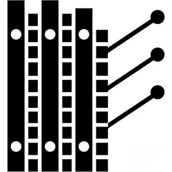
Drainage Layout Design

Weep grid laid out per AASHTO LRFD §11.10.8 and FHWA spacing guidance, typically 5 to 10 ft horizontal and 6 to 10 ft vertical, with closer spacing in zones of expected high seepage.

2

Pipe Installation

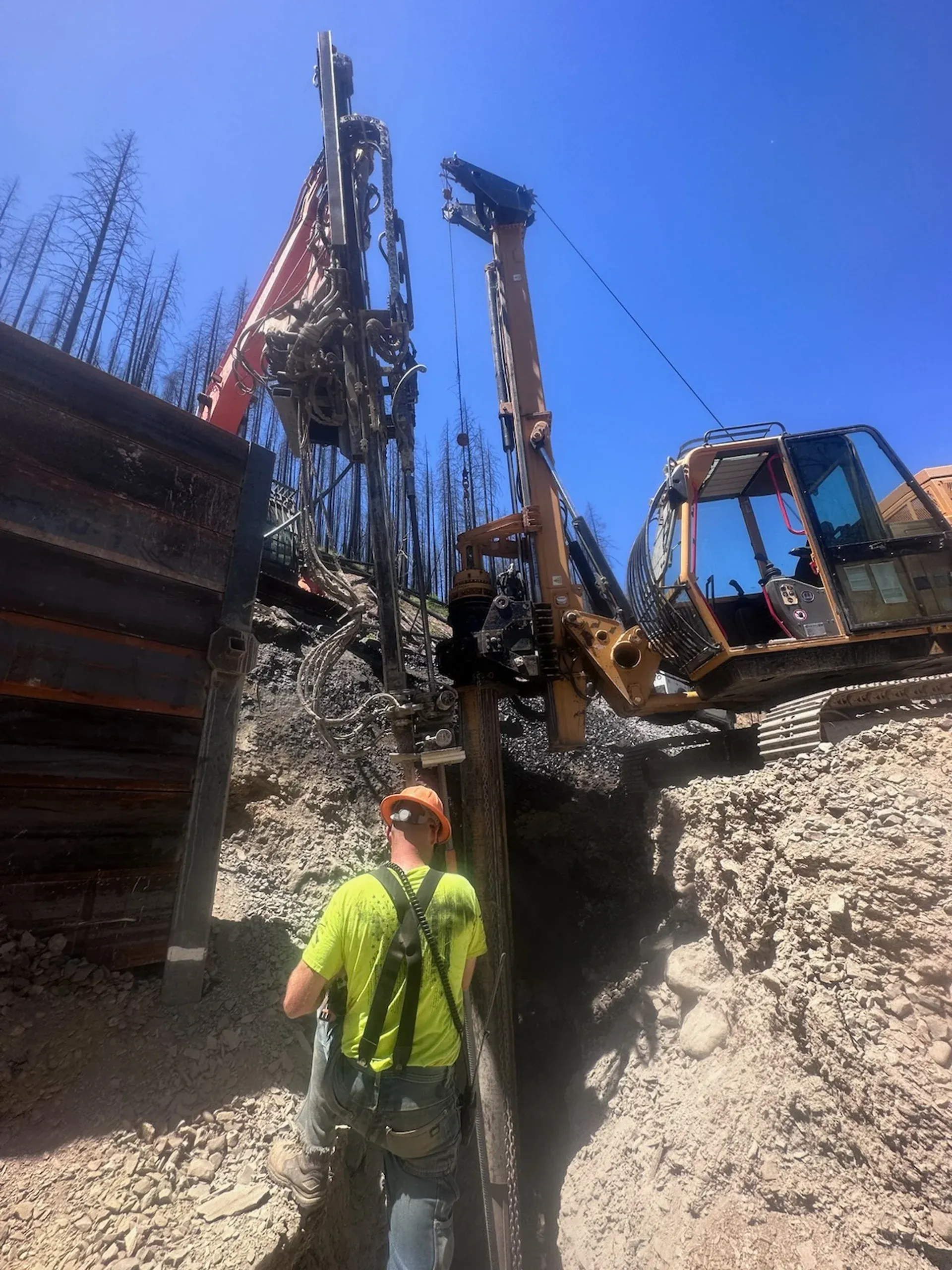
2 to 4 inch schedule 40 PVC pipes set through formwork before shotcrete or precast placement, or core-drilled through existing facings for retrofit.

3

Filter Protection

AASHTO M 288 Class 2 nonwoven geotextile filter sock or graded gravel pack per AASHTO M 43 wraps the back end of each pipe to prevent soil migration into the drain.

4

Outlet Detailing

Pipes set at 2 to 5 percent downward gradient, with outlets projecting 6 to 12 inches beyond the facing and terminated at a splash block or rip-rap apron for staining control.

5

Coordination with Chimney and Blanket Drains

On engineered walls, weeps daylight the flow collected by a chimney and blanket aggregate drainage system, designed as a hierarchy per AASHTO and FHWA practice.

System Variants

Types of Weep Drain Systems

Type 01

Through-Facing PVC Weeps

The standard detail across shotcrete soil nail walls, structural shotcrete facings, and block retaining walls. A schedule 40 PVC pipe (typically 2 to 4 in diameter) is set in the formwork before shotcrete placement, or core-drilled through the facing for retrofit on existing walls. The back end is wrapped in an AASHTO M 288 Class 2 nonwoven geotextile filter sock, or surrounded by a graded gravel pack per AASHTO M 43 (No. 57 or No. 67 open-graded stone), to prevent soil migration and clogging. The outlet projects 6 to 12 inches beyond the facing and is often terminated with a splash block to control staining and erosion at the discharge point.

Type 02

Prefabricated Geocomposite Weep Elements

Manufactured drainage units, including products like Mirafi G-Series, J-Drain, and Hydraway geocomposites, combine a vertical drainage strip on the back of the facing with an integral through-wall outlet. The geocomposite core (typically a dimpled HDPE sheet or a three-dimensional polymer mesh) wrapped in a nonwoven geotextile filter replaces the field-built chimney drain on tight-clearance backfilled walls, then daylights through the facing at the prescribed weep spacing. Common on production MSE walls and constrained-backfill block walls where graded aggregate placement is impractical, with the entire system specified to ASTM D6707 transmissivity criteria.

Type 03

Chimney and Blanket Drain to Outlet Weep

The full backfilled-wall drainage system AASHTO LRFD §11.10.8 calls for. A chimney drain of clean open-graded aggregate (typically AASHTO M 43 No. 57) is placed immediately behind the wall facing and extended down to a horizontal blanket drain at the wall base. A perforated PVC or HDPE outlet pipe in the blanket drain conveys collected flow laterally to discharge points, and through-facing weeps daylight any residual water at the facing. Used on MSE walls, soldier pile walls with shotcrete or precast facings, and bridge abutments where the design pore pressure must be controlled across the entire reinforced or backfilled zone, not just at the facing.

Side By Side

Weep Drains vs Other Drainage Systems

VS

Weep Drain vs Horizontal Drain

A weep drain is a short (12 to 36 inch) through-facing relief at the wall, while a horizontal drain is a long (50 to 500 plus ft) drilled hole that intercepts the groundwater table within the slope or wall mass. The two operate at different scales of the drawdown problem. Weeps relieve seepage that has already reached the facing; horizontal drains lower the regional water table before it pressurizes the system. On a saturated cut slope or a landslide site, the horizontal drain is the primary tool (it does the work of dewatering the soil mass), and weeps are the finishing detail that keeps any residual seepage off the facing. The two are usually paired, not substituted, on a comprehensive slope or wall drainage design.

VS

Weep Drain vs Chimney Drain

The chimney drain is the collection system, the weep drain is the outlet. A chimney is a vertical column of clean open-graded aggregate, or a geocomposite drainage panel, placed against the back of the wall facing, and a blanket drain extends laterally along the wall base. Together they collect water from the reinforced or backfilled zone and route it to the wall face. Without the weep drain, the chimney has no place to discharge; without the chimney, the weep relieves only random water that happens to reach the facing through soil pathways. AASHTO LRFD §11.10.8 specifies the full chimney, blanket, and weep system as a unit on permanent backfilled walls, not weeps in isolation.

VS

Weep Drain vs French Drain

A french drain is a buried perforated pipe set in graded aggregate, used to collect subsurface water before it reaches the wall, while a weep drain discharges water at the wall face. They serve complementary roles. A french drain at the wall toe, or in a foundation excavation, intercepts groundwater migrating laterally through the surrounding soil; weeps daylight any water that bypasses the french drain and reaches the facing. On wet-soil sites, both are usually specified, with the french drain reducing the volume the weeps must handle and the weeps providing the safety relief if the french drain clogs or its capacity is exceeded.

Not sure which system fits? We'll walk through the tradeoffs for your site conditions.

Talk Through Your Options
Where It Fits

Where Weep Drains Are Used

Weep drains are a near-universal detail on permanent retaining and stabilized-slope structures. On MSE walls, the weep is the discharge point for the chimney and blanket drain that AASHTO LRFD §11.10.8 specifies behind the facing panels. On shotcrete-faced soil nail walls, FHWA GEC-7 calls for through-facing weeps at 5 to 10 ft spacing to prevent the hydrostatic head that drives shotcrete debonding. On soldier pile walls, weeps daylight seepage through the lagging or shotcrete facing between piles, and on structural shotcrete applications, weeps are the only thing standing between the facing and freeze-thaw spalling caused by trapped backfill water.

Beyond walls, weeps appear on bridge abutments and wing walls, tunnel portals, segmental block retaining walls (where NCMA SRW design specifies weep spacing comparable to FHWA practice), and on landslide remediation sites where they pair with horizontal drains as a two-stage drainage strategy. On rehabilitation projects, weeps are routinely retrofitted into existing walls by core drilling through the facing and installing PVC pipes with geotextile filter, restoring drainage capacity to walls that have begun to show water staining, efflorescence, or facing distress.

MSE walls and bridge abutments
Shotcrete-faced soil nail walls
Soldier pile walls with timber lagging or shotcrete facing
Structural shotcrete on cut slopes
Tunnel portals and wing walls
Segmental block retaining walls
Landslide remediation sites paired with horizontal drains
Rehabilitation retrofits on existing walls showing seepage distress
Benefits

Key Advantages

Code-Required Drainage

Permanent retaining wall drainage is mandated by AASHTO LRFD §11.10.8 and detailed by FHWA-NHI-10-024 and FHWA GEC-7. Weep drains are not optional, they are the discharge component of the system.

Prevents Hydrostatic Failure

Hydrostatic pressure behind walls is the leading cause of retaining wall failure. Weeps hold the back-of-wall pore pressure at or near zero, eliminating the load that drives wall tilt and structural distress.

Simple, Verifiable Detail

PVC pipes installed during construction add minimal cost while providing significant long-term protection, and visible flow at outlets confirms the system is working without instrumented monitoring.

Extends Wall Life

Proper drainage prevents freeze-thaw damage, shotcrete debonding, efflorescence, and structural distress, extending the service life of the facing system to 75 plus years.

Low Maintenance

Passive drains require only periodic inspection of outlets and occasional flushing in fine-grained soils to maintain capacity over the design life.

Engineering

Technical Considerations

Soil/Rock Conditions

Weep drains work in any soil or rock condition where water accumulates behind facing systems. Filter geotextile or gravel pack gradation is matched to the backfill or retained soil to prevent fines migration without restricting flow.

Groundwater

Drains must be sized and spaced for the expected water inflow. Sites with high groundwater or perched water tables typically require supplemental horizontal drains to lower the regional water table within the slope mass before water reaches the facing.

Load Capacity

Not applicable, weep drains provide drainage and pressure relief, not structural support.

Spacing

Standard 5 to 10 ft horizontal and 6 to 10 ft vertical grid per FHWA-NHI-10-024 and FHWA GEC-7. Closer spacing is used near the wall base where the chimney drain concentrates flow, in zones of observed high seepage, and on cold-climate sites for ice-blockage redundancy.

Installation Method

PVC pipes set through formwork before shotcrete or precast placement on new construction, or core-drilled through existing facings for retrofit. Filter sock or graded gravel pack installed at the back end before the drain is sealed into the facing.

Equipment Used

  • 2 to 4 in schedule 40 PVC pipe
  • AASHTO M 288 Class 2 nonwoven geotextile filter sock
  • Open-graded gravel for filter pack (AASHTO M 43 No. 57 or No. 67)
  • Core drill for retrofit installations
  • Splash blocks or rip-rap aprons for outlet termination

Limitations

  • Must be installed at proper elevation and gradient for gravity flow
  • Filter protection is critical, unfiltered drains clog quickly with fines
  • Cold-climate detailing required to prevent freeze-thaw blockage
  • May require supplemental horizontal drains where groundwater volumes are high

Technical Specifications

Pipe Size
2" to 4" Schedule 40 PVC
Grid Spacing
5 to 10 ft horizontal (FHWA / AASHTO)
Filter
AASHTO M 288 Class 2 geotextile sock or AASHTO M 43 gravel pack
Slope
2% to 5% downward to daylight
Codes And References

Engineering Standards and References

AASHTO

LRFD §11.10.8

Drainage for Retaining Walls

Section 11.10.8 of the AASHTO LRFD Bridge Design Specifications mandates drainage behind permanent retaining structures, specifying chimney and blanket drains with weep outlets to prevent hydrostatic loading on the wall facing.

FHWA

NHI-10-024

MSE Walls and Reinforced Soil Slopes Design Manual

Berg, Christopher, and Samtani 2009. Volume I details the full drainage hierarchy for MSE walls (chimney and blanket aggregate drains, perforated outlet pipes, and through-facing weeps) with typical horizontal weep spacing of 5 to 10 ft.

FHWA

GEC-7 (NHI-14-007)

Soil Nail Walls Reference Manual

Lazarte et al. 2015. Specifies through-facing weeps on shotcrete-faced soil nail walls to relieve hydrostatic pressure and prevent the back-of-facing water column that causes shotcrete debonding and facing detachment.

AASHTO

M 288

Geotextile Specification for Highway Applications

Sets filter geotextile classes used in weep drain construction. Class 2 nonwoven geotextile is the standard wrap for PVC weep pipes and chimney drain envelopes on permanent retaining walls.

Expertise

Why Choose Rock Supremacy for Weep Drains

Code-Compliant Drainage Detail

Weep grids designed and installed to AASHTO LRFD §11.10.8, FHWA-NHI-10-024 for MSE walls, and FHWA GEC-7 for shotcrete-faced soil nail walls.

AASHTO M 288 Filter Specification

Class 2 nonwoven geotextile filter socks or graded gravel packs per AASHTO M 43, the standard filter protection for permanent retaining wall drainage.

Positive Gradient and Outlet Detailing

Drains set at 2 to 5 percent downward gradient with outlets daylighted 6 to 12 inches beyond the facing for staining control and verifiable gravity flow.

Drainage System Coordination

Through-facing weeps, chimney and blanket drains, and horizontal drains designed as one drainage hierarchy, not in isolation.

Questions

Weep Drains FAQ

A weep drain is a short through-facing drainage outlet, typically a 2 to 4 inch schedule 40 PVC pipe with a geotextile filter sock, installed through a retaining wall, MSE wall, soldier pile wall, or shotcrete-faced soil nail wall to discharge water that has collected behind the facing. The pipe is set on a 5 to 10 ft grid with a 2 to 5 percent downward gradient toward daylight, so collected seepage drains by gravity. Weep drains are the discharge point for the chimney and blanket drainage system AASHTO LRFD §11.10.8 specifies on permanent retaining walls.
Hydrostatic pressure is the leading cause of retaining wall failure, and AASHTO LRFD §11.10.8 makes wall drainage a design requirement, not an option. Without a weep drain, water trapped behind the facing builds a pressure column that drives wall tilt, shotcrete debonding, freeze-thaw spalling, and outright structural failure. The weep drain relieves that water column by daylighting collected seepage at a regular grid across the facing, holding the back-of-wall pore pressure at or near zero throughout the service life of the wall.
Standard horizontal spacing is 5 to 10 feet across the wall facing, with vertical spacing of 6 to 10 feet up the wall height. FHWA-NHI-10-024 specifies 5 to 10 ft horizontal weep spacing for MSE walls, and FHWA GEC-7 calls for similar spacing on shotcrete-faced soil nail walls. Closer spacing is used in zones of high seepage, near the wall base where the chimney drain concentrates flow, and in cold-climate sites where ice blockage of any single drain would compromise the system.
Yes. Weep drains are routinely retrofitted into existing retaining walls, soldier pile walls, and shotcrete facings by core drilling through the facing, installing a 2 to 4 inch PVC pipe with a geotextile filter sock or graded gravel pack at the back end, and sealing the wall penetration. Retrofits are common on rehabilitation projects where the original drainage has clogged, the wall was built without weeps, or new seepage has appeared after a change in upslope drainage or groundwater conditions.
An AASHTO M 288 Class 2 nonwoven geotextile filter sock, or a graded gravel filter pack per AASHTO M 43 (typically a No. 57 or No. 67 open-graded stone), wraps the back end of the drain pipe, keeping fines out of the perforations while allowing water through. The filter is sized to the soil gradation behind the wall, finer soils require finer geotextile or a graded transition pack, and uniform coarse soils tolerate larger filter openings. Periodic outlet inspection and occasional flushing keep the system free of biofilm or root intrusion over the design life.
Properly detailed drains continue to operate through freeze-thaw cycles, but the detail matters in cold climates. The pipe is sloped 2 to 5 percent downward so water does not pond inside the drain, the outlet is set above the splash zone so daylighted water cannot freeze back into the pipe, and in deep-frost regions the back end of the drain is set below the frost line to keep the bonded soil-filter zone unfrozen. Closer weep spacing also provides redundancy, if a single drain ices over for part of the winter, adjacent drains carry the flow.
They solve different problems. A weep drain is a short (12 to 36 inch) through-facing relief detail that handles water that has already reached the back of the wall, and is required on virtually every permanent retaining and shotcrete-faced wall. A horizontal drain is a long (50 to 500 plus ft) drilled hole that intercepts the groundwater table within the slope or wall mass, used when the regional water table is the actual driver of instability. On a saturated cut slope or a landslide site, both are usually specified, horizontal drains lower the water table within the soil mass, weeps daylight any residual seepage at the new facing.
The primary references are AASHTO LRFD §11.10.8 (drainage requirements for retaining walls), FHWA-NHI-10-024 (MSE Walls and Reinforced Soil Slopes Design and Construction Guidelines, Berg, Christopher, Samtani 2009), and FHWA-NHI-14-007 / GEC-7 (Soil Nail Walls Reference Manual, Lazarte et al. 2015). AASHTO M 288 specifies the filter geotextile classes used in the drain construction, and AASHTO M 43 governs graded aggregate gradations for chimney and blanket drains. NCMA's Segmental Retaining Wall design manual specifies comparable weep details for block retaining walls.
No, they are paired components of the same system. The chimney drain is the collection element, a vertical column of clean open-graded aggregate (or a geocomposite drainage panel) placed against the back of the wall facing that conveys water down to a horizontal blanket drain at the wall base. The weep drain is the discharge element, a through-facing pipe that daylights the water the chimney has collected. AASHTO LRFD §11.10.8 specifies the full chimney, blanket, and weep system as a unit on permanent backfilled walls. Weeps in isolation only relieve random water that happens to reach the facing through soil pathways, not water collected from the entire backfill zone.
Testimonials

Client Testimonials

Trusted by DOTs, engineering firms, and property owners nationwide.

Contact

Deploy Us

Ready to discuss your project? Our team is standing by to assess your site conditions and develop a custom solution using Weep Drains and other proven techniques.

Emergency (24/7)

(541) 383-7625

Bidding & Estimates

Info@RockSupremacy.com

Headquarters

Western Division (HQ)
65147 N Hwy 97
Bend, OR 97701
Eastern Division
915 Millennium Ct
Blountville, TN 37617

Licensed in CO, UT, WY, ID, MT, CA, WA, OR, TN, VA

Request Consultation