Tunnel Support Systems

Tunnel Support Systems

Tunnel support systems are the engineered ground-control elements that stabilize an underground opening through excavation and into permanent service: steel rib sets, lattice girders embedded in shotcrete, pattern rock bolts with welded wire mesh, and pre-support canopies. FHWA NHI-10-034 and USACE EM 1110-2-2901 govern design selection by ground class.

W6-W14
Steel Sections
3-6 ft
Set Spacing
RMR / Q
Ground Class
FHWA NHI-10-034
Design Reference
Overview

Understanding Tunnel Support Systems

Tunnel support systems are the engineered ground-control elements that stabilize an underground opening from the moment of excavation through long-term service. The right system depends on rock-mass quality (Bieniawski RMR or Barton Q ground classification), tunnel geometry, and service environment. Heavy rock bolt patterns with structural shotcrete linings handle good-to-fair rock; lattice girders embedded in shotcrete carry the load on moderate ground under New Austrian Tunneling Method (NATM) practice; W-section steel rib sets, blocked-and-lagged on 3 to 6 ft centers, hold squeezing or fault-zone ground; spiling and forepoling pre-support the face on portal cuts and weak crowns.

We deliver tunnel support work on active rail and highway corridors where production windows are measured in hours and service interruptions are non-negotiable. Our crews self-perform the drilling, steel erection, shotcrete placement, and contact grouting required to close behind primary support. FHWA NHI-10-034 governs civil road tunnel design; USACE EM 1110-2-2901 governs tunnels and shafts in rock; MSHA 30 CFR §57.3360 governs mining ground support, with shotcrete cores tested per ASTM C1604.

What Are Tunnel Support Systems?

Tunnel support systems are the engineered structural elements installed inside an underground opening to control ground movement during excavation and to carry permanent rock and soil loads through the design service life. Two distinct service stages share the same family of elements. Initial or primary support is installed immediately behind the advancing face to close the excavation perimeter before convergence becomes large enough to fail the rock arch; final lining is the durable structural shell, typically reinforced shotcrete or cast-in-place concrete, that carries long-term loads after primary support has stabilized the ground. The same job often combines elements from both stages.

The major support elements are steel rib sets (W6 to W14 sections blocked-and-lagged on 3 to 6 ft centers), lattice girders (lightweight steel triangulated frames embedded in shotcrete), pattern rock bolts with welded wire mesh, structural shotcrete linings, and pre-support canopies (spiling and forepoling). Selection is driven by rock-mass quality classified through the Bieniawski Rock Mass Rating (RMR) or the Barton Q-System, by tunnel geometry, and by service environment. FHWA NHI-10-034 sections 6 and 10, USACE EM 1110-2-2901, and AFTES (Association Française des Tunnels et de l'Espace Souterrain) recommendations together define the design and construction envelope for civil tunnel support.

Key Benefits

  • Immediate ground capacity upon installation
  • Adjustable to changing rock-mass conditions
  • Pre-support extends safe advance through weak ground
  • Compatible with NATM and conventional methods
  • Documented century-plus service life on rehabilitated tunnels
The Engineering

How Tunnel Support Is Designed and Installed

How the system carries load in service, and how we build it on site.

Design begins with ground characterization. Geotechnical investigation produces a rock-mass quality profile along the alignment, classified through Bieniawski RMR (rated 0 to 100 across strength, RQD, joint spacing, joint condition, and groundwater) or Barton Q (a multiplicative product of six ground parameters). Each ground class maps to a recommended support pattern: pattern rock bolts and shotcrete for RMR 60 plus, lattice girders with shotcrete and bolts for RMR 30 to 60, heavy W-section steel ribs at close spacing for RMR below 30 or for squeezing ground. Stand-up time, the interval between excavation and rock self-failure, drives how quickly support must be closed behind the face.

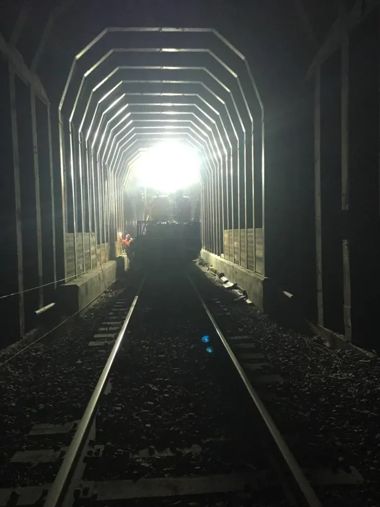
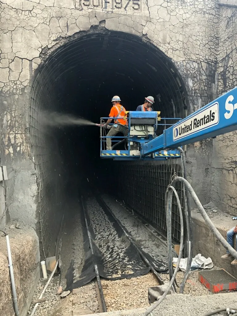
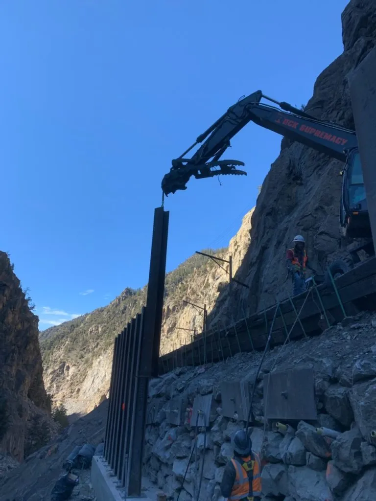
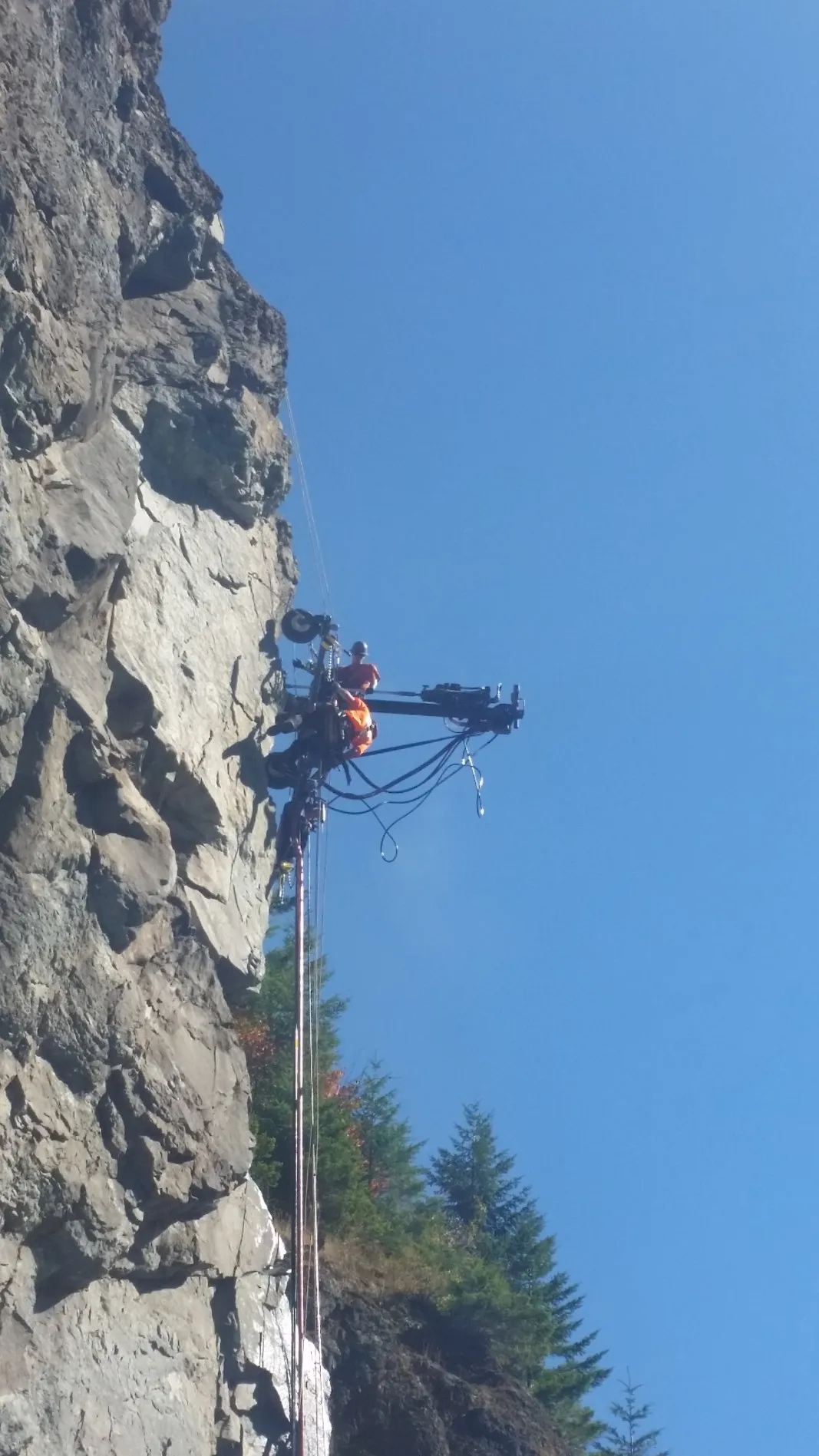
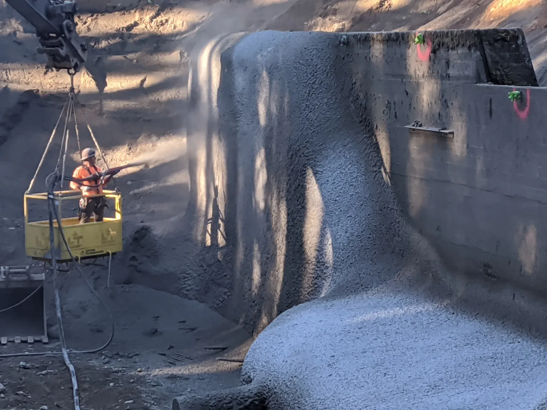
Construction proceeds in a measured sequence. Excavation advances by drill-and-blast, roadheader, or full-face TBM. Initial support is installed within the unsupported span, typically a single round in poor ground or a few rounds in competent rock. Steel rib sets are erected, blocked tight to the rock with timber or grout bags, and lagged with timber, steel, or shotcrete between sets to transfer ground loads to the ribs. Lattice girders are placed and a shotcrete lift is shot to encase them, embedding the girder as integral reinforcement of the shotcrete shell. Pattern rock bolts are drilled and grouted to confine the rock arch immediately behind the face, with mesh and shotcrete forming the continuous shell across the bolt heads.

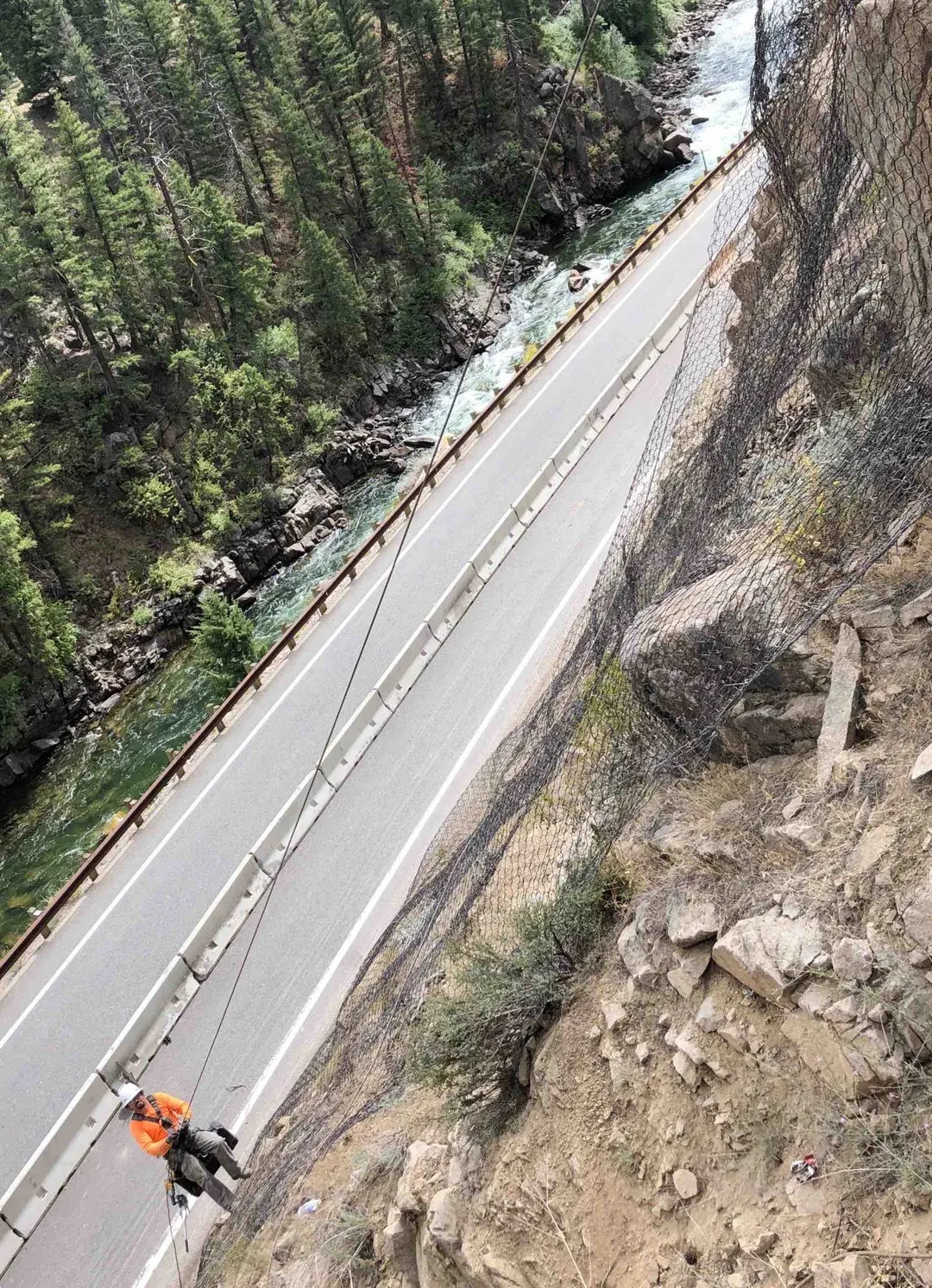
Convergence monitoring drives the staged decision-making. Survey targets installed inside the support measure crown drop, sidewall closure, and invert heave; readings inform whether the chosen support is adequate or whether the section must be reinforced. Once primary support has stabilized convergence (typically days to weeks depending on ground class), contact grouting fills voids behind lagging or shotcrete, the invert is closed, and the final lining is constructed. Quality control verifies steel section size, set spacing, rib alignment, blocking contact, lagging coverage, shotcrete thickness, and bolt installation per the project ground-support drawings.

1

Ground Characterization

Classify rock-mass quality (Bieniawski RMR or Barton Q) and select support pattern per FHWA NHI-10-034 or USACE EM 1110-2-2901.
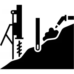
2

Set or Girder Erection

Position multi-piece W-section ribs or lattice girders at design spacing and connect with splice plates and tie rods.
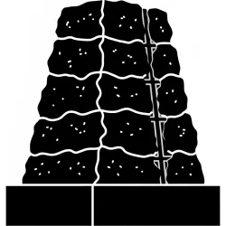
3

Blocking and Lagging

Tighten crown blocking against rock and install lagging (steel, timber, or shotcrete) between sets to transfer ground load.
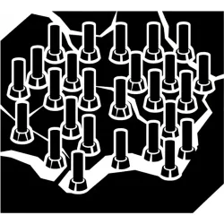
4

Bolting and Shotcrete

Drill and grout pattern rock bolts; place welded wire mesh; shoot structural shotcrete in lifts of 2 to 4 inches per ASTM C1604 acceptance.

5

Convergence Monitoring

Track crown drop, sidewall closure, and invert heave on survey targets to confirm primary support has stabilized the ground.

System Variants

Tunnel Support System Variations

Type 01

Steel Rib Sets (W-Section Ribs With Lagging)

Steel rib sets are the workhorse for poor ground, fault zones, squeezing rock, and rehabilitation of deteriorating tunnels. W-section structural steel (typically W6 through W14, ASTM A992 Grade 50) is rolled to the tunnel arch profile and erected as multi-piece rings on 3 to 6 ft centers, with closer spacing in the worst ground. Crown blocking with timber, grout-filled fabric bags, or shotcrete pillows tightens each set against the rock; lagging spans between sets to transfer ground load to the steel. Steel rib support has been continuously used for over 150 years and remains the design choice when ground loads are large enough to demand high stiffness or when rapid emergency stabilization is the controlling constraint. The trade-off is reduced clearance, mechanical handling weight, and slower advance compared to NATM bolt-and-shotcrete shells.

Type 02

Lattice Girders Embedded in Shotcrete (NATM Standard)

Lattice girders are lightweight triangulated steel frames, typically formed of three or four longitudinal bars connected by zigzag lacing bars, that combine the rib geometry of a steel set with the shotcrete-integration of NATM construction. The girder is erected in the same arch position as a rib set, then encased in structural shotcrete in successive lifts so the steel becomes integral reinforcement of the shotcrete shell. Lattice girders weigh roughly one-third of an equivalent W-section rib, simplifying handling in confined cross-sections and short work windows, and they shotcrete more easily because the open lattice eliminates the encapsulation shadows that congested rebar grids create. NATM road tunnels under FHWA NHI-10-034 routinely use lattice girders as the primary rib element on moderate ground, with pattern rock bolts and welded wire mesh completing the composite shell.

Type 03

Rock Bolts With Shotcrete and Welded Wire Mesh

Pattern rock bolting with welded wire mesh and structural shotcrete is the standard composite shell for good-to-fair rock (RMR 50 plus) and the production approach for most modern hard-rock tunnels. Bolts confine the rock arch immediately behind the face, suspending loose blocks from the intact mass and converting a discontinuous jointed system into a coherent reinforced beam. Welded wire mesh fastened to the bolt heads catches small spalls and reinforces the shotcrete face. Structural shotcrete, typically 4 to 8 inches thick in two or more lifts, forms the continuous reinforced shell across the bolt heads and seals the rock from atmospheric weathering. The system is light, fast, and adaptable to changing ground because additional bolts and shotcrete thickness can be added in real time as conditions evolve.

Type 04

Pre-Support Canopies (Spiling, Forepoling, Pipe Roof)

Pre-support is installed ahead of the advancing face, not behind it, to provide an umbrella that holds weak ground above the crown until primary support can be erected behind the round. Spiling consists of small-diameter rebar dowels driven or grouted at a shallow upward angle into the face crown ahead of excavation. Forepoling uses larger-diameter steel pipes or threaded bars on similar geometry, often grouted in place for greater stiffness. Pipe-roof canopies use 4 to 12 inch diameter steel pipes drilled and grouted from the face on 12 to 24 inch spacing, forming a horizontal canopy 30 to 60 ft long that lets the tunnel advance through soft ground, fault crossings, and shallow-cover portals where stand-up time would otherwise be inadequate. Pre-support is combined with steel rib sets, lattice girders, or bolt-and-shotcrete shells as the primary support behind the advancing face.

Side By Side

Tunnel Support System Comparisons

VS

Steel Rib Sets vs Lattice Girders

The defining trade-off is stiffness against shotcrete-integration. W-section rib sets deliver maximum stiffness and immediate load capacity at the cost of handling weight, clearance loss, and lagging-and-blocking labor. Lattice girders weigh roughly one-third as much, simplify handling, and become integral reinforcement of the surrounding shotcrete shell rather than a separate steel-and-lagging system. The penalty for lattice girders is lower bare-steel stiffness before shotcrete cures and less load capacity in extreme squeezing ground or fault crossings. The selection rule of thumb: use rib sets where ground loads exceed what NATM lattice-and-shotcrete can carry, where rapid emergency stabilization is the constraint, or where rehabilitation work demands the heaviest available support. Use lattice girders for new NATM construction on moderate ground where shotcrete-integrated support gives the most efficient cross-section.

VS

Bolt-and-Shotcrete Shell vs Heavy Rib Sets

Pattern rock bolting with shotcrete and mesh is the production approach for good-to-fair rock; heavy rib sets are the production approach for poor-to-squeezing ground. The bolt-and-shotcrete shell wins on advance rate, clearance, material cost, and adaptability to changing ground (more bolts, thicker shotcrete added in real time). Rib sets win on immediate load capacity, predictable performance in fault zones, and rapid emergency stabilization where ground will not stand long enough for bolts to be drilled and grouted. Ground classification (Bieniawski RMR or Barton Q) maps the breakpoint: RMR 50 plus typically uses bolt-and-shotcrete; RMR below 30 uses heavy ribs at close spacing; the transition zone uses lattice girders with shotcrete and supplemental bolts.

VS

Initial Support vs Final Lining

The defining difference is design intent and service stage. Initial or primary support is installed immediately behind the face to control convergence in the construction stage; it must be erected fast and must close the perimeter before the rock fails by gravity raveling or stand-up-time exhaustion. Final lining is the long-term durable shell, typically reinforced shotcrete or cast-in-place concrete, designed to carry permanent ground loads, withstand groundwater chemistry, and present a smooth interior surface for the tunnel's service function. The two stages share elements (lattice girders embedded in initial shotcrete often remain part of the structural cross-section under the final lining) but differ in design loading: initial support resists construction-stage convergence; final lining resists fully developed long-term ground pressure plus seismic and hydrostatic demands.

Not sure which system fits? We'll walk through the tradeoffs for your site conditions.

Talk Through Your Options
Where It Fits

Where Tunnel Support Systems Are Used

Railroad tunnel rehabilitation is a dominant application. Class I railroads operate hundreds of pre-1900 timber-and-masonry tunnels that require steel rib reinforcement, shotcrete encasement, and crown reconstruction to extend service life through another century, almost always under continuing rail traffic with work windows measured in hours. Highway tunnels, both new construction and rehabilitation, use the same support family: NATM bolt-and-shotcrete shells with lattice girders for new alignments, and steel ribs with shotcrete encasement for rehabilitation of older drill-and-blast tunnels. Tunnel rehabilitation is the umbrella service through which we coordinate ground investigation, structural reinforcement, drainage, and lining replacement on aging infrastructure.

Mining drift and shaft support governed by MSHA 30 CFR §57.3360 uses pattern rock bolts, mesh, and shotcrete for primary ground control, with steel sets installed at portals, fault crossings, and intersections. Water-conveyance tunnels (penstocks, water-supply, sewer interceptors) use lattice girders and shotcrete for primary support, with cast-in-place concrete or steel-pipe linings for the durable hydraulic surface. Portal stabilization uses pre-support canopies (spiling, forepoling, pipe roof) combined with soil nailing in soil-overburden zones and rock bolts in rock cuts. Emergency stabilization of failing tunnels under traffic, where rapid mobilization of steel sets and shotcrete crews is the controlling constraint, is a recurring scope for our crews.

New tunnel excavation support
Rail and highway tunnel rehabilitation
Portal and shaft stabilization
Underground mining drifts
Fault zone and squeezing ground
Emergency tunnel ground control
Benefits

Key Advantages

Immediate Load Capacity

Steel rib sets and grouted rock bolts develop their full design capacity within hours of installation, the controlling property in deteriorating ground and emergency stabilization.

Ground-Class Adaptable

Set spacing, section size, bolt pattern, and shotcrete thickness are adjusted in real time as RMR or Q ratings change along the alignment.

Pre-Support Capability

Spiling, forepoling, and pipe-roof canopies extend safe advance through weak portals, fault crossings, and shallow-cover sections that would otherwise fail stand-up time.

Standards-Cited Design

Support patterns, materials, and acceptance testing follow FHWA NHI-10-034, USACE EM 1110-2-2901, MSHA 30 CFR §57.3360, ASTM A992, and ASTM C1604.

Documented Service Life

Steel rib support has been continuously used in tunnels for over 150 years; properly encased ribs in rehabilitated tunnels routinely deliver century-plus service life.

Engineering

Technical Considerations

Soil/Rock Conditions

Support type and spacing selected from Bieniawski RMR or Barton Q ground classification. Poor-to-squeezing ground requires close-spaced W-section ribs; good rock typically uses pattern bolts and shotcrete; transition zones use lattice girders with shotcrete and supplemental bolts.

Groundwater

Drainage provisions are integrated with the support system. Weep holes through shotcrete relieve hydrostatic buildup; pressure grouting consolidates fractured ground and seals water inflows behind primary support.

Load Capacity

Steel section size and rib spacing are determined by computed ground loads. Lattice girders embedded in shotcrete provide equivalent capacity to W-section ribs with substantially lower handling weight.

Spacing

Set spacing is typically 3 to 6 ft. Closer spacing applies in fault zones, shallow cover, or squeezing ground; wider spacing applies in better rock where the ribs supplement a bolt-and-shotcrete shell.

Installation Method

Sets or lattice girders erected immediately following each excavation round. Crown blocked tight to the rock; lagging installed between sets. Pattern rock bolts drilled and grouted to the bolt schedule. Structural shotcrete applied in lifts of 2 to 4 inches per ASTM C1604 acceptance criteria.

Equipment Used

  • Set erector or boom-mounted positioner
  • Production rock drills for bolt installation
  • Wet-mix or dry-mix shotcrete pump and delivery system
  • Blocking, lagging, and grout-bag inventory
  • Survey instrumentation for convergence monitoring

Limitations

  • Heavy W-section ribs require mechanical handling
  • Rib profile reduces tunnel clearance
  • Encased ribs require corrosion protection for permanent service
  • Production rate slower than bare bolt-and-shotcrete shells
  • Pre-support canopies require drilling access ahead of the face

Technical Specifications

Steel Sections
W6 to W14 (ASTM A992 Grade 50)
Set Spacing
3 ft to 6 ft typical
Lagging
Steel / Timber / Shotcrete
Blocking
Timber / Grout-filled fabric / Shotcrete pillows
Codes And References

Engineering Standards and References

FHWA

NHI-10-034

Technical Manual for Design and Construction of Road Tunnels (Civil Elements)

Canonical US reference for civil tunnel design and construction. Sections 6 and 10 cover initial support (steel ribs, lattice girders, rock bolts, shotcrete) and final lining design, with detailing for NATM and conventional construction methods.

USACE

EM 1110-2-2901

Engineering and Design: Tunnels and Shafts in Rock

US Army Corps of Engineers manual covering rock-mechanics design of tunnels and shafts. Treats ground classification (RMR, Q-system), support selection, instrumentation and monitoring, and the staged construction sequence from primary support through final lining.

MSHA

30 CFR §57.3360

Ground Support Use

Federal mining regulation requiring ground support where ground conditions or mining method warrant. Establishes the regulatory framework for pattern rock bolting, screen, shotcrete, and rib sets in mine drifts and shafts under Mine Safety and Health Administration jurisdiction.

ASTM

ASTM A992

Standard Specification for Structural Steel Shapes

Material specification for the W-section structural steel used in tunnel rib sets. Grade 50 (50 ksi yield, 65 ksi tensile) is the dominant grade for civil tunnel rib applications. Lattice girder bars typically conform to ASTM A615 reinforcing steel grades.

Gallery

Our Work in Action

Expertise

Why Choose Rock Supremacy for Tunnel Support

Active-Corridor Tunnel Work

Tunnel rehabilitation work in active corridors requires shift-block coordination, strict flagging protection, and short nighttime work windows. Our crews are equipped and trained for the production protocols these constraints demand.

Coordinated Tunnel Trades

Drilling, steel erection, shotcrete placement, and pressure grouting are coordinated under one project team to reduce coordination gaps during constrained work windows.

Emergency Mobilization

Rapid mobilization capability for emergency tunnel stabilization, with steel-set fabrication, shotcrete, and pressure-grouting equipment configured for emergency deployment.

Confined Space and MSHA Trained

Crews hold confined-space, MSHA 30 CFR §46/§48, and rope-access certifications required for safe work in active tunnels, mine drifts, and shafts.

Standards-Cited Quality Control

Set alignment, blocking contact, lagging coverage, shotcrete thickness, and bolt installation are documented per FHWA NHI-10-034 and ASTM C1604 acceptance criteria on every project.

Questions

Tunnel Support Systems FAQ

Tunnel support systems are the engineered structural elements installed inside an underground opening to control ground movement during excavation and to carry permanent rock and soil loads through the design service life. The major elements are W-section steel rib sets, lattice girders embedded in shotcrete, pattern rock bolts with welded wire mesh, structural shotcrete linings, and pre-support canopies (spiling, forepoling, pipe roof). FHWA NHI-10-034 and USACE EM 1110-2-2901 govern selection by ground class through Bieniawski RMR or Barton Q rock-mass classification.
Ground classification drives the choice. Good-to-fair rock (Bieniawski RMR 50 plus) typically uses pattern rock bolts with welded wire mesh and structural shotcrete as a composite shell. Poor-to-squeezing ground (RMR below 30) typically uses W-section steel rib sets at 3 to 4 ft spacing because the bolt-and-shotcrete shell cannot mobilize enough capacity fast enough. Transition zones (RMR 30 to 60) use lattice girders embedded in shotcrete with supplemental rock bolts. Emergency stabilization of deteriorating tunnels typically defaults to steel ribs because they develop their full capacity immediately after installation.
NATM is a tunnel construction philosophy developed in the 1960s that uses the rock mass itself as the primary load-carrying element. Initial support is installed quickly behind the face (lattice girders embedded in shotcrete, pattern rock bolts, welded wire mesh), and convergence is measured through survey targets to confirm the rock-and-support system is reaching equilibrium. The final lining is constructed only after primary support has stabilized the ground. NATM contrasts with traditional rib-and-lagging construction by treating support as part of a deformable composite system rather than a stiff prop holding the full ground load.
A lattice girder is a lightweight triangulated steel frame, typically formed of three or four longitudinal bars connected by zigzag lacing bars, that combines the rib geometry of a steel set with shotcrete-integration. The girder is erected at the design rib position, then encased in structural shotcrete in successive lifts so the steel becomes integral reinforcement of the shotcrete shell. Lattice girders weigh roughly one-third of an equivalent W-section rib, simplifying handling and shotcrete encapsulation. They are the standard primary-rib element on NATM road tunnels under FHWA NHI-10-034.
Spiling and forepoling are pre-support methods installed ahead of the advancing face to provide a canopy that holds weak ground above the crown until primary support can be erected. Spiling uses small-diameter rebar dowels driven or grouted at a shallow upward angle into the face crown. Forepoling uses larger-diameter steel pipes or threaded bars on similar geometry, often grouted in place. Pipe-roof canopies use 4 to 12 inch diameter steel pipes drilled and grouted on close spacing to form a horizontal canopy 30 to 60 ft long. Pre-support is essential for soft-ground portals, fault crossings, and shallow-cover sections where stand-up time would otherwise be inadequate.
Emergency mobilization is within 24 to 48 hours for failing tunnels where rapid ground control is the controlling constraint. Production installation rates depend on tunnel size, ground class, and available work windows. New-construction NATM advance with lattice girders, shotcrete, and bolts typically progresses 5 to 15 ft per round depending on ground quality. Rehabilitation work in active corridors progresses within the constraints of available shift-block windows, which can be as short as 2 hours.
Yes. Class I railroad tunnel rehabilitation is routinely performed under traffic with proper flagging protection and pre-coordinated shift-block work windows. Crews stage materials, erect support, and clear the tunnel between scheduled trains, often in 2-hour nighttime blocks. Pre-fabricated steel sets, quick-setting shotcrete, and rapid-deployment crews are essential because every block ends with a fully restored running clearance and an accurate hand-off to railroad operations.
Properly installed steel rib sets encased in structural shotcrete deliver century-plus service life; many original 19th-century rail tunnels retain their first-installation steel ribs in functioning condition after rehabilitation. Lattice girders embedded in shotcrete share the design life of the surrounding shotcrete shell, typically 75 to 100 years for well-detailed civil construction. Service life is governed primarily by corrosion control on the steel and by the integrity of the surrounding shotcrete or final lining.
Common causes include corrosion from sustained water infiltration through cracked linings, increased ground loads from surface development or seismic events, loss of blocking contact behind ribs as timber rots or grout bags compress, deterioration of timber lagging, and progressive shotcrete delamination from the rock substrate. Most rehabilitation work addresses these causes simultaneously: replacement steel reinforcement, contact grouting to reseat blocking, drainage upgrades to control groundwater, and shotcrete overlay to restore the structural shell.
FHWA NHI-10-034 (Technical Manual for Design and Construction of Road Tunnels) is the canonical US civil reference, with sections 6 and 10 covering initial support and final lining. USACE EM 1110-2-2901 (Tunnels and Shafts in Rock) covers rock-mechanics design, ground classification, instrumentation, and the staged construction sequence. MSHA 30 CFR §57.3360 governs ground support in mining drifts and shafts. ASTM A992 specifies structural steel for W-section rib material; ASTM C1604 specifies the test method for drilled shotcrete cores used in acceptance testing.
Testimonials

Client Testimonials

Trusted by DOTs, engineering firms, and property owners nationwide.

Contact

Deploy Us

Ready to discuss your project? Our team is standing by to assess your site conditions and develop a custom solution using Tunnel Support Systems and other proven techniques.

Emergency (24/7)

(541) 383-7625

Bidding & Estimates

Info@RockSupremacy.com

Headquarters

Western Division (HQ)
65147 N Hwy 97
Bend, OR 97701
Eastern Division
915 Millennium Ct
Blountville, TN 37617

Licensed in CO, UT, WY, ID, MT, CA, WA, OR, TN, VA

Request Consultation

Methods

Related Techniques

Explore other engineering methods we use to deliver comprehensive geotechnical solutions.